Product Description
Gear coupling flexible Fluid Flange HRC Spacer PIN MH Rigid NM Jaw Steel chain brake standard drum wheel rolling shaft steel transmission parts
Ever-Power industry is 1 of the biggest couplings manufacturer in China, have already exported lots of gear couplings, Jaw couplings, chain couplings etc.. to Japan, Korea, Italy , USA …..
Application of Gear coupling
Gear couplings are used to connect 2 shafts that are not perfectly aligned. They do this by using gears to transmit torque between the shafts. Gear couplings are available in a variety of sizes and types, and they are used in a wide range of applications.
Some of the most common applications for gear couplings include:
- Pumps: Gear couplings are used to connect the motor to the pump in a variety of pumps, including centrifugal pumps, positive displacement pumps, and gear pumps.
- Fans: Gear couplings are used to connect the motor to the fan in a variety of fans, including centrifugal fans, axial fans, and propeller fans.
- Compressors: Gear couplings are used to connect the motor to the compressor in a variety of compressors, including reciprocating compressors, rotary screw compressors, and centrifugal compressors.
- Machine tools: Gear couplings are used to connect the motor to the machine tool in a variety of machine tools, including lathes, mills, and drills.
- Conveyors: Gear couplings are used to connect the motor to the conveyor in a variety of conveyors, including belt conveyors, bucket conveyors, and screw conveyors.
Gear couplings offer a number of advantages over other types of couplings, including:
- High torque capacity: Gear couplings can transmit high torque, which is necessary for applications where a lot of force needs to be applied.
- Good alignment tolerance: Gear couplings can tolerate misalignment, which is necessary for applications where the shafts may not be perfectly aligned.
- Long life: Gear couplings have a long life, which is necessary for applications where the coupling needs to operate for a long time.
- Low noise: Gear couplings operate quietly, which is important for applications where noise is a concern.
- Versatility: Gear couplings can be used in a variety of applications.
If you need a coupling that can transmit high torque, tolerate misalignment, and have a long life, then a gear coupling may be the right solution for you.
thumb_upthumb_down
uploa
Main range of Couplings
/* January 22, 2571 19:08:37 */!function(){function s(e,r){var a,o={};try{e&&e.split(“,”).forEach(function(e,t){e&&(a=e.match(/(.*?):(.*)$/))&&1

Role of Fluid Couplings in Heavy-Duty Mining Equipment
Fluid couplings play a critical role in heavy-duty mining equipment, offering several advantages that enhance the performance, safety, and longevity of the machinery:
- Soft Start: In mining applications, where large equipment like crushers, conveyors, and draglines are involved, fluid couplings provide a soft start to the motor, gradually ramping up the torque and reducing the shock and stress on the drivetrain. This ensures smoother equipment startup and prevents sudden power demand spikes.
- Torque Limiting: Fluid couplings act as torque limiters, protecting the equipment from sudden overloads and torque surges during operations. This feature prevents damage to the motor, gearbox, and driven components, thus increasing the reliability and lifespan of the equipment.
- Load Distribution: In mining equipment with multiple driven components or motors, fluid couplings enable efficient load distribution among the components. This ensures that each component shares the load appropriately, preventing uneven wear and improving overall system efficiency.
- Overload Protection: The inherent slip feature of fluid couplings allows them to slip at high loads, providing overload protection to the equipment. In case of unexpected jams or blockages in conveyor belts or crushers, the fluid coupling can slip, preventing costly damage to the equipment.
- Vibration Damping: Mining operations can generate significant vibrations that can be damaging to the equipment. Fluid couplings help dampen vibrations, reducing stress on the components and minimizing wear and tear.
- Reduced Maintenance: By preventing sudden torque surges and overloads, fluid couplings reduce the need for frequent maintenance and repairs, saving both time and money for mining operators.
Heavy-duty mining equipment operates in harsh and challenging environments with high loads and abrasive materials. Fluid couplings used in mining applications are designed to be robust, durable, and resistant to contaminants like dust and water.
Overall, fluid couplings play a vital role in ensuring the efficient and reliable operation of heavy-duty mining equipment, contributing to increased productivity and reduced downtime in mining operations.
Cost Implications of Using Fluid Couplings in Comparison to Other Power Transmission Methods
The cost implications of using fluid couplings in power transmission depend on various factors, including the application requirements, the size of the system, and the operational conditions. While fluid couplings offer several advantages, they may have different cost considerations compared to other power transmission methods like mechanical clutches, VFDs (Variable Frequency Drives), and direct mechanical drives.
1. Initial Investment:
The initial cost of a fluid coupling can be higher than that of a mechanical clutch or a direct mechanical drive. Fluid couplings contain precision components, including the impeller and turbine, which can impact their initial purchase price.
2. Maintenance Costs:
Fluid couplings are generally considered to have lower maintenance costs compared to mechanical clutches. Mechanical clutches have wear and tear components that may require more frequent replacements, leading to higher maintenance expenses over time.
3. Energy Efficiency:
Fluid couplings are highly efficient in power transmission, especially during soft-start applications. Their ability to reduce shock loads and provide a smooth acceleration can result in energy savings and operational cost reductions.
4. Space and Weight:
Fluid couplings are usually more compact and lighter than some mechanical clutches, which can be advantageous in applications with space constraints or weight limitations.
5. Specific Application Considerations:
The suitability and cost-effectiveness of fluid couplings versus other power transmission methods can vary based on specific application requirements. For example, in soft-start applications, fluid couplings may be the preferred choice due to their ability to reduce mechanical stress and protect connected equipment.
6. Lifespan and Reliability:
While the initial cost of a fluid coupling might be higher, their longevity and reliability can lead to lower overall life cycle costs compared to other power transmission methods.
In conclusion, the cost implications of using fluid couplings in power transmission depend on the particular application and the total cost of ownership over the equipment’s lifespan. Although fluid couplings may have a higher initial investment, their long-term reliability, energy efficiency, and lower maintenance costs can make them a cost-effective choice in many industrial applications.

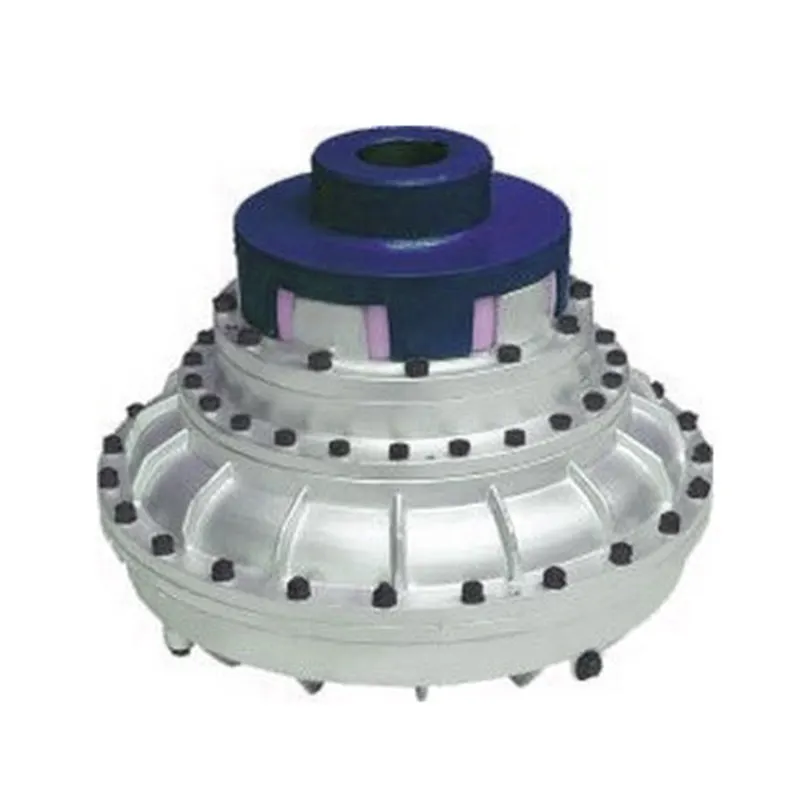
Principle of Hydrodynamic Fluid Coupling
A hydrodynamic fluid coupling operates on the principle of hydrokinetics, utilizing hydraulic fluid to transmit power between an engine or prime mover and a driven load. The key components of a fluid coupling are the impeller, the turbine, and the housing filled with hydraulic fluid.
Here’s how the principle works:
- Impeller: The impeller is connected to the engine’s crankshaft and is responsible for driving the hydraulic fluid. As the impeller rotates, it creates a flow of fluid within the housing.
- Fluid Flow: The rotational motion of the impeller causes the fluid to move radially outward, towards the housing walls. This generates a high-velocity fluid flow in the housing.
- Turbine: The turbine is connected to the driven load, such as a transmission or machinery input shaft. As the fluid flows onto the blades of the turbine, it causes the turbine to rotate.
- Power Transmission: The kinetic energy of the high-velocity fluid is transferred to the turbine, resulting in the rotation of the driven load. The power transmission is achieved purely through the hydrodynamic effect of the fluid flow.
- Slip: In a fluid coupling, there is always a slight difference in speed (slip) between the impeller and the turbine. This slip is necessary to allow the fluid to accelerate from rest to the speed of the turbine. As a result, the output speed of the driven load is always slightly less than the input speed from the engine.
Hydrodynamic fluid couplings provide several advantages, such as smooth power transmission, overload protection, and torsional vibration dampening. However, they do not provide torque multiplication like torque converters do, making them more suitable for applications where precise speed matching is required.


editor by CX 2024-05-17
China Custom Flexible Gear Coupling Fluid Flange HRC Spacer Pin Mh Rigid Nm Jaw Steel Chain Brake Standard Drum Wheel Rolling Shaft Steel Transmission Parts
Product Description
Gear coupling flexible Fluid Flange HRC Spacer PIN MH Rigid NM Jaw Steel chain brake standard drum wheel rolling shaft steel transmission parts
Ever-Power industry is 1 of the biggest couplings manufacturer in China, have already exported lots of gear couplings, Jaw couplings, chain couplings etc.. to Japan, Korea, Italy , USA …..
Application of Gear coupling
Gear couplings are used to connect 2 shafts that are not perfectly aligned. They do this by using gears to transmit torque between the shafts. Gear couplings are available in a variety of sizes and types, and they are used in a wide range of applications.
Some of the most common applications for gear couplings include:
- Pumps: Gear couplings are used to connect the motor to the pump in a variety of pumps, including centrifugal pumps, positive displacement pumps, and gear pumps.
- Fans: Gear couplings are used to connect the motor to the fan in a variety of fans, including centrifugal fans, axial fans, and propeller fans.
- Compressors: Gear couplings are used to connect the motor to the compressor in a variety of compressors, including reciprocating compressors, rotary screw compressors, and centrifugal compressors.
- Machine tools: Gear couplings are used to connect the motor to the machine tool in a variety of machine tools, including lathes, mills, and drills.
- Conveyors: Gear couplings are used to connect the motor to the conveyor in a variety of conveyors, including belt conveyors, bucket conveyors, and screw conveyors.
Gear couplings offer a number of advantages over other types of couplings, including:
- High torque capacity: Gear couplings can transmit high torque, which is necessary for applications where a lot of force needs to be applied.
- Good alignment tolerance: Gear couplings can tolerate misalignment, which is necessary for applications where the shafts may not be perfectly aligned.
- Long life: Gear couplings have a long life, which is necessary for applications where the coupling needs to operate for a long time.
- Low noise: Gear couplings operate quietly, which is important for applications where noise is a concern.
- Versatility: Gear couplings can be used in a variety of applications.
If you need a coupling that can transmit high torque, tolerate misalignment, and have a long life, then a gear coupling may be the right solution for you.
thumb_upthumb_down
uploa
Main range of Couplings

Factors Influencing the Thermal Performance of a Fluid Coupling
The thermal performance of a fluid coupling, specifically its ability to dissipate heat and maintain operating temperatures within acceptable limits, is influenced by several factors:
- Power Rating: The power rating of the fluid coupling, which indicates its capacity to handle a specific amount of power, affects its thermal performance. Higher power ratings generally result in higher heat generation, so it’s essential to choose a fluid coupling with an adequate power rating for the application.
- Operating Speed: The operating speed of the fluid coupling is a critical factor. Higher speeds can lead to increased heat generation due to friction and viscous losses. It’s essential to consider the operating speed to ensure the fluid coupling can handle the heat produced at the given speed.
- Ambient Temperature: The ambient temperature of the environment in which the fluid coupling operates also plays a role in its thermal performance. Higher ambient temperatures can impact the cooling efficiency and may lead to increased operating temperatures.
- Load Variation: Applications with varying loads can experience changes in heat generation. Fluid couplings used in such systems must be capable of handling the thermal effects of load fluctuations without exceeding temperature limits.
- Cooling Method: The cooling method employed in the fluid coupling design significantly affects its thermal performance. Some fluid couplings use natural convection for cooling, while others incorporate forced cooling methods such as internal or external cooling circuits. The cooling system’s efficiency directly impacts the ability to dissipate heat effectively.
- Fluid Properties: The properties of the fluid inside the coupling, such as viscosity and heat capacity, influence thermal performance. The choice of fluid can affect the amount of heat generated and the efficiency of heat dissipation.
- Operating Time: The duration of operation also affects the thermal behavior of the fluid coupling. Continuous operation or extended duty cycles may lead to higher operating temperatures, requiring careful consideration during selection.
- Proper Maintenance: Regular maintenance, including lubricant inspection and replacement, is crucial for optimal thermal performance. Contaminated or degraded fluid can impact the heat transfer characteristics of the coupling.
It’s essential to consider these factors when selecting a fluid coupling to ensure that it can effectively manage heat generation and maintain safe operating temperatures in the specific application.
Fluid Coupling’s Handling of Load Changes during Operation
Fluid couplings are designed to efficiently handle changes in load conditions during operation, providing smooth and controlled power transmission. Here’s how fluid couplings accomplish this:
1. Torque Sensing: Fluid couplings are torque-sensitive devices. As the load on the driving side varies, the torque transmitted through the fluid coupling adjusts accordingly. When the load increases, the fluid coupling allows for some slip between the input and output sides, absorbing the excess torque. Conversely, when the load decreases, the fluid coupling reduces slip and transmits more torque, accommodating the new load conditions.
2. Load Distribution: In multi-drive systems, fluid couplings help to distribute the load evenly among connected equipment. When one machine experiences a higher load, the fluid coupling redistributes torque to prevent overloading of a specific component, ensuring a balanced power distribution.
3. Smooth Power Transmission: Fluid couplings offer a smooth and gradual transmission of power, even during load changes. Unlike mechanical clutches or direct couplings, fluid couplings provide a dampening effect, reducing shock loads and torsional vibrations when the load fluctuates. This minimizes stress on the connected machinery and enhances overall system reliability.
4. Soft Start and Stop: One of the significant advantages of fluid couplings is their ability to facilitate soft start and stop operations. During startup, the fluid coupling allows for controlled slip, gradually increasing the speed of the driven equipment. Similarly, during shutdown, the fluid coupling smoothly decelerates the connected machinery, preventing sudden stops that could cause damage or excessive wear.
5. Overload Protection: In situations where the load surpasses the rated capacity, the fluid coupling acts as an overload protector. By slipping and absorbing excess torque, it prevents damage to the connected equipment and the fluid coupling itself. This overload protection contributes to the safety and longevity of the entire system.
6. Automatic Adjustment: Fluid couplings automatically adjust to variations in load conditions without the need for manual intervention. This feature makes them suitable for applications with changing load demands, such as conveyors, crushers, pumps, and fans.
Overall, the ability of fluid couplings to handle changes in load conditions ensures stable and efficient power transmission while protecting the machinery from abrupt stress and wear. This makes fluid couplings an excellent choice for various industrial applications that require reliable and flexible power transfer.
Fluid Couplings and Energy Efficiency in Power Transmission
Fluid couplings play a significant role in improving energy efficiency in power transmission systems. They achieve this by enabling smooth and efficient torque transmission while reducing energy losses during various operating conditions.
One of the key factors contributing to the energy efficiency of fluid couplings is their hydrodynamic principle of operation. When power is transmitted through a fluid coupling, it operates on the principle of hydrodynamic power transmission. The primary component, known as the impeller, rotates and imparts motion to the fluid inside the coupling. This motion creates a hydrodynamic force that transmits the torque to the output side.
During the initial startup or when there is a significant speed difference between the input and output shafts, the fluid coupling allows the input shaft to accelerate gradually. This feature, known as the soft start, reduces the mechanical stress on the connected components and the power source. By avoiding sudden acceleration, fluid couplings minimize the energy spikes that occur during direct starts in systems without couplings.
Moreover, fluid couplings act as a torque limiter when the load exceeds a certain threshold. This characteristic, known as the slip, allows the fluid coupling to disengage slightly when the torque reaches a predetermined level. As a result, it protects the system from overloads and reduces energy wastage during high-stress conditions.
Additionally, fluid couplings help mitigate the impact of shock loads and torsional vibrations, which can reduce wear and tear on mechanical components. By minimizing vibrations and shock loads, fluid couplings contribute to longer equipment life and, consequently, lower maintenance and replacement costs.
However, it’s important to note that like any mechanical component, fluid couplings have some energy losses due to viscous drag and heat dissipation. While modern fluid couplings are designed with improved efficiency, these losses need to be considered when assessing the overall energy efficiency of a power transmission system.
In summary, fluid couplings enhance energy efficiency in power transmission by providing soft starts, torque limiting, and damping of vibrations, thus reducing energy wastage and extending the life of the connected equipment.
editor by CX 2023-08-07
Double made in China – replacement parts – in Jeonju Republic of Korea Steel Spur Gear Stable Supplied Precision Powder Metallurgy Gear with ce certificate top quality low price


We – EPG Group the bigge EPT Chain and agricultural gearbox manufacturing unit in China with 5 various branches. For a lot more information: Cellular/whatsapp/telegram/Kakao us at: 0086~13083988828 13858117778 0571 88828
Positive aspects&colon
1&interval Professional gears producer
two&periodExperienced in Cooperate with massive Companies
3&period of time Specialist gears EPT Ability
four&periodStable gears Quality
5&periodReasonable gears Rates
six&periodSmall gears Orders Recognized
seven&periodContinuous gears quality advancements
eight&time period Higher gears high quality Overall performance
9&periodShort gears lead time and shipment
ten&periodProfessional gears support
We can provide with sample for quality and purpose screening&time period
Product Description&colon
| Material | Carbon Steel | SAE1571&comma SAE1045&comma Cr12&comma 40Cr&comma Y15Pb&comma 1214Letc | |
| Alloy Stee | 20CrMnTi&comma 16MnCr5&comma 20CrMnMo&comma 41CrMo&comma 17CrNiMo5etc | ||
| Brass&solBronze | HPb59-1&comma H70&comma CuZn39Pb2&comma CuZn40Pb2&comma C38000&comma CuZn40etc | ||
| Type | Bevel Gear | ||
| Treatment | Heat treatment options&comma Carburizing&comma Sharpening | ||
| Standard | ISO &solR 606 | ||
| Machining approach | fabrication&commastamping&commadeep drawing&commagear hobbing&comma gear milling&comma gear shaping&comma machining and assembly gear broaching&comma gear grinding and gear gaping | ||
| Module | 1&period0&comma 1&period25&comma 1&period5&comma 1&period75&comma 2&period0&comma 2&period25&comma 2&period5&interval&period of time&time period&period8&period0 and so on | ||
| Tolerance control | Outer Diameter&colon&pm0&period005mm | Length Dimension&colon&pm0&period05 mm | |
| Tooth accuracy | GB1244-eighty five&comma DIN8188&comma ISO&solR 606 &comma ANSI B 29&period1M | ||
| Warmth therapy | Quenching & Tempering&comma Carburizing & Quenching&comma Large-frequency Hardening&comma Carbonitriding&period&period of time&interval | ||
| Floor treatment method | Blacking&comma Sprucing&comma Anodization&comma Chrome plating&comma Zinc plating&comma Nickel plating&interval&time period&period of time | ||
Our company has a variety of imported higher-precision processing equipment&comma sophisticated creation technology &commaimprove the signifies of detection&comma a sound merchandise high quality management technique&comma for customers ca EPT 1st-class good quality &interval
Our Service
1&periodOEM&colon According to your drawings and samples demands&period of time
two&periodManufacturer with aggressive price and high quality&period of time
three&time period one hundred&percnt inspection ahead of shipping and delivery&period of time
four&period Convenient transportation&interval
5 &periodGood packing&time period
6&period Small gears Orders Recognized&period of time
7&period Rich knowledgeable staff Professional technical help and resolution staff
Packaging & Delivery&colon
Packaging Particulars&colon Plastic bag inner and regular carton outer or as per
client’s requires
Supply Element&colon Delivered in 20-30 days after advance TT payment
If there are any concerns or need our aid&comma please get in touch with with us with no be reluctant &comma or you can deliver a message
The use of original equipment manufacturer’s (OEM) element figures or emblems , e.g. CASE® and John Deere® are for reference purposes only and for indicating product use and compatibility. Our firm and the shown substitution components contained herein are not sponsored, accepted, or created by the OEM.


Coating made in China – replacement parts – in Baixada Santista Brazil Gear Pumps Wholesalers with ce certificate top quality low price
We – EPG Team the bigge EPT Chain and agricultural gearbox factory in China with 5 distinct branches. For a lot more information: Mobile/whatsapp/telegram/Kakao us at: 0086~13083988828 13858117778 0571 88828
Coating Gear Pumps Wholesalers
A.[Item Description]
The design utilizes high standard external spur gears enclosed within a close tolerance housing assembly. This supplies you the exact volume of fluid dispensed per shaft revolution. The housing is built from a precision floor and lapped 3-plate assembly. This assembly is aligned with dowe EPT to permit close control of working clearances. This construction approach in mixture with several proprietary inner attributes is what makes certain exact, pulseless and reliable stream below varying method problems. When HangZhou Instrument pumps are coupled with a pre-packaged, built-in, closed-loop speed control and a compact motor driver assembly (AC or DC), HangZhou Instrument is capable to supply the mo EPT precise and adaptable metering gear pump technique on the industry.
B.[Parameters]
| Design |
Displacement (CC/R) |
Overall Height | Foundation Top | Min Inlet Pressure | Max Outpet Force | Precision | Temperature |
| GWMP-.fifteen | .15 | 83 | 28.one | <0.2Mpa | <30Mpa | +/-3% | 200ºC |
|
GWMP-.three |
.three | eighty five | thirty.2 | <0.2Mpa | <30Mpa | +/-3% | 200ºC |
| GWMP-.six | .six | eighty five | 32 | <0.2Mpa | <30Mpa | +/-3% | 200ºC |
| GWMP-1.2 | one.2 | 90 | 34 | <0.2Mpa | <30Mpa | +/-3% | 200ºC |
| GWMP-2.4 | two.4 | a hundred | forty two | <0.2Mpa | <30Mpa | +/-3% | 200ºC |
| GWMP-3.six | three.six | a hundred and five | fifty | <0.2Mpa | <30Mpa | +/-3% | 200ºC |
| GWMP-six | 6 | 130 | forty one | <0.2Mpa | <30Mpa | +/-3% | 200ºC |
| GWMP-9 | nine | 135 | 46 | <0.2Mpa | <30Mpa | +/-3% | 200ºC |
| GWMP-12 | twelve | 140 | 51 | <0.2Mpa | <30Mpa | +/-3% | 200ºC |
| GWMP-fifteen | fifteen | one hundred forty five | 56 | <0.2Mpa | <30Mpa | +/-3% | 200ºC |
| GWMP-twenty | twenty | a hundred and fifty | 64 | <0.2Mpa | <30Mpa | +/-3% | 200ºC |
| GWMP-thirty | 30 | a hundred sixty five | 80 | <0.2Mpa | <30Mpa | +/-3% | 200ºC |
| GWMP-forty | 40 | ninety | 215 | <0.2Mpa | <30Mpa | +/-3% | 200ºC |
| GWMP-50 | fifty | ninety seven | 215 | <0.2Mpa | <30Mpa | +/-3% | 200ºC |
| GWMP-60 | sixty | 104.five | 230 | <0.2Mpa | <30Mpa | +/-3% | 200ºC |
| GWMP-seventy five | 75 | 112 | 230 | <0.2Mpa | <30Mpa | +/-3% | 200ºC |
| GWMP-80 | eighty | Custom-made | Custom-made | <0.2Mpa | <30Mpa | +/-3% | 200ºC |
| GWMP-one hundred twenty five | a hundred twenty five | Custom-made |
Personalized |
<0.2Mpa | <30Mpa | +/-3% | 200ºC |
Note:Course of rotation: clockwise from the axis of rotation
| Design | 6CC | 9CC | 12CC | 15CC | 20CC | 25CC | 30CC |
| A | a hundred thirty | a hundred thirty five | a hundred and forty | 145 | one hundred fifty | 158 | a hundred sixty five |
| B | 41 | forty six | 51 | 56 | sixty four | seventy two | 80 |
| Min Inlet Pressure | <0.2Mpa |
| Doing work Speed | 5~200 R/min |
| Medium | Fluid |
| Temperature | 200ºC |
| Max Outlet Force | <30Mpa |
| Movement Capability | 6-thirty(+/-30)CC/R |
| Sealing | Mixed seal |
| Model | .15CC | .3CC | .6CC | one.2CC | 2.4CC | 3.2CC | three.6CC |
| A | 83 | eighty five | 85 | ninety | 100 | 103 | one hundred and five |
| B | 28.1 | thirty.2 | 32 | 34 | forty two | forty seven.6 | 50 |
| Min Inlet Strain | <0.2Mpa |
| Functioning Velocity | 5~200 R/min |
| Medium | Fluid |
| Temperature | 200ºC |
| Max Outlet Force | <30Mpa |
| Flow Potential | .15-3.6(+/-3%)cc/r |
| Sealing | Combined |
C.[Installation]
D.[Company Information]
- Our Organization is Top 10 Manufacture on Alibaba
- We have about 30 many years of encounter in Manufacture
- Our products have been exported to much more 100 coutries and region
- ISO,SGS,CE and much more ceterficates for you reference
- Patent technologies and far more than 3 years doing work life
The use of authentic equipment manufacturer’s (OEM) portion figures or logos , e.g. CASE® and John Deere® are for reference functions only and for indicating merchandise use and compatibility. Our firm and the outlined alternative components contained herein are not sponsored, accepted, or produced by the OEM.
1-9W made in China – replacement parts – in Pyongyang Dem. People’s Republic of Korea DC Square Gear Motor Cast Gear with ce certificate top quality low price
We – EPG Team the bigge EPT Chain and agricultural gearbox manufacturing facility in China with 5 distinct branches. For a lot more particulars: Cellular/whatsapp/telegram/Kakao us at: 0086~13083988828 13858117778 0571 88828
1-9W DC Sq. Equipment Motor Ca EPT Equipment (AF-545)
DC Geared Motor for gold mining Equipment (AF-545)
AF-545
1) Electrical power: 1-9W
two) Voltage: 3 – 36V DC
3) Output pace: 1-100 rpm
4) Reduction ratio: 1: seventy three, 1: one hundred thirty five, 1: 174, 1: 252, 1: 391, 1: 506, 1: 730
five) Motor proportions: Dia 35.8mm*50.5mm
Gearbox proportions: 47mm*seventy one.5mm
Output shaft standard length: 8mm DIA
6) Standard Software: Pan/Tilt Digital camera, car shutter, welding equipment, water meter, IC card, grill, oven, cleansing equipment, garbage disposers, family appliances, slot machinery, cash detector, automated actuator, coffee device, towel disposal, lighting, coin refund gadgets, peristaltic pump.
7) Packing Information: CTN Dimension: 55*35*18cm, 24 pcs/CTN, N. W. 14KGS.
Firm Introduction
The use of original tools manufacturer’s (OEM) element quantities or emblems , e.g. CASE® and John Deere® are for reference reasons only and for indicating solution use and compatibility. Our business and the shown substitution elements contained herein are not sponsored, accepted, or manufactured by the OEM.