Product Description
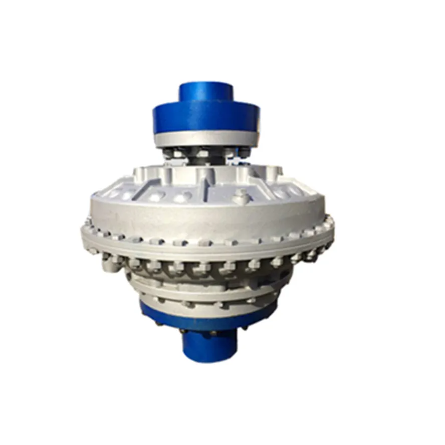
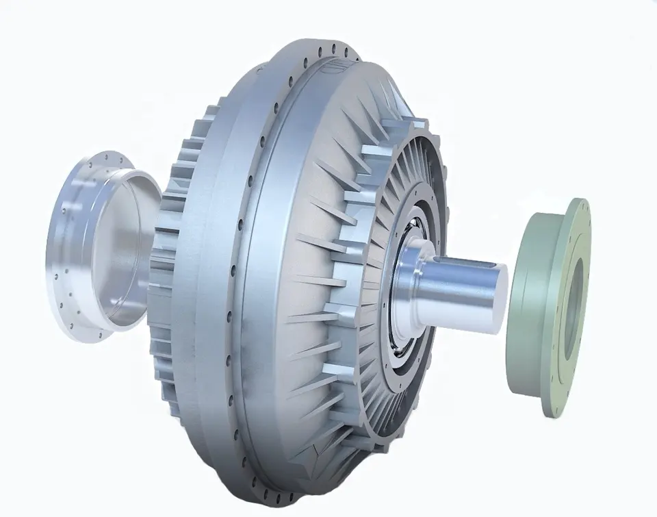
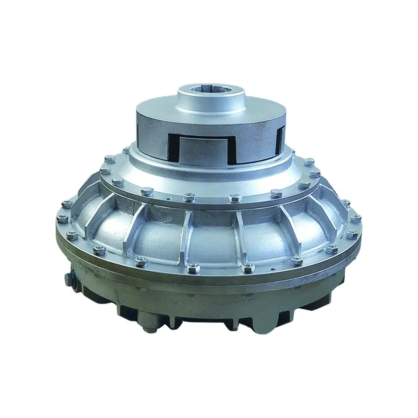
Densen Customized Scraper hydraulic coupling,pressure relief type hydraulic coupling,torque limiting fluid coupling
| Product Name | Scraper hydraulic coupling,pressure relief type hydraulic coupling,torque limiting fluid coupling |
| DN mm | 16~190mm |
| Rated Torque | 40~25000 N·m |
| Allowable speed | 4500~200 kN·m |
| Material | 45#steel,aluminum |
| Application | Widely used in metallurgy, mining, engineering and other fields. |
Product show
Company Information
Equipment
Application Case
Typical case of diaphragm coupling applied to variable frequency speed control equipment
JMB type coupling is applied to HangZhou Oilfield Thermal Power Plant
According to the requirements of HangZhou Electric Power Corporation, HangZhou Oilfield Thermal Power Plant should dynamically adjust the power generation according to the load of the power grid and market demand, and carry out the transformation of the frequency converter and the suction fan. The motor was originally a 1600KW, 730RPM non-frequency variable speed motor matched by HangZhou Motor Factory. The speed control mode after changing the frequency is manual control. Press the button speed to increase 10RPM or drop 10RPM. The coupling is still the original elastic decoupling coupling, and the elastic de-coupling coupling after frequency conversion is frequently damaged, which directly affects the normal power generation.
It is found through analysis that in the process of frequency conversion speed regulation, the pin of the coupling can not bear the inertia of the speed regulation process (the diameter of the fan impeller is 3.3 meters) and is cut off, which has great damage to the motor and the fan.
Later, they switched to the JMB460 double-diaphragm wheel-type coupling of our factory (patent number: ZL.99246247.9). After 1 hour of destructive experiment and more than 1 year of operation test, the equipment is running very well, and there is no Replace the diaphragm. 12 units have been rebuilt and the operation is in good condition.
Other Application Case
Spare parts
Packaging & Shipping
Contact us

Can you explain the Concept of Slip in a Fluid Coupling?
In a fluid coupling, slip refers to the relative speed difference between the impeller and the runner. When the impeller, which is connected to the driving shaft, rotates, it induces the flow of hydraulic fluid inside the coupling. This fluid flow in turn drives the rotation of the runner, which is connected to the driven shaft.
However, due to the operating principle of fluid couplings, there is always a certain amount of slip between the impeller and the runner. This slip occurs because the fluid coupling needs to allow for a small speed difference in order to transmit torque smoothly.
During startup or under heavy load conditions, the impeller’s rotational speed may be slightly higher than the runner’s rotational speed. This speed difference causes the hydraulic fluid to circulate between the impeller and the runner, generating hydrodynamic forces that transmit torque from the driving shaft to the driven shaft.
Slip is an inherent and controlled characteristic of fluid couplings, and it is essential for their smooth operation. However, excessive slip can lead to energy losses and reduced efficiency. Therefore, fluid couplings are designed to have an optimal slip value for specific applications, balancing the need for torque transmission and energy efficiency.

Special Considerations for Using Fluid Couplings in Explosive Environments
Fluid couplings are widely used in various industrial applications, including those in potentially explosive environments. When considering the use of fluid couplings in such settings, several special considerations must be taken into account to ensure safety and compliance with regulations:
- Explosion-Proof Design: Fluid couplings used in explosive environments must be designed to prevent the ignition of flammable gases or vapors. They should adhere to explosion-proof standards and be equipped with robust seals and protective enclosures to contain any potential sparks or flames.
- Ingress Protection: An appropriate ingress protection (IP) rating is essential to prevent dust, moisture, or other hazardous substances from entering the fluid coupling. A higher IP rating ensures greater protection against potential sources of ignition.
- Material Selection: The choice of materials for the fluid coupling is crucial in explosive environments. Non-sparking or anti-static materials should be used to reduce the risk of ignition caused by friction or electrical discharge.
- Temperature Limitations: Fluid couplings operating in explosive environments must have temperature ratings that prevent overheating and potential ignition of flammable substances. The fluid coupling should be adequately cooled to maintain safe operating temperatures.
- Monitoring and Maintenance: Regular monitoring and maintenance of fluid couplings in explosive environments are essential. Periodic inspections can detect potential issues or wear that could compromise the safety of the coupling. Any maintenance or repair work should be carried out by qualified personnel following safety protocols.
- Compliance with Regulations: Depending on the industry and location, there may be specific regulations and safety standards that govern the use of equipment in explosive atmospheres. It is crucial to adhere to these regulations and ensure that the fluid coupling complies with all relevant safety requirements.
Fluid couplings used in explosive environments play a vital role in ensuring the safe and reliable operation of industrial machinery. By providing smooth and controlled power transmission, fluid couplings can help minimize risks and improve the overall safety of the equipment and personnel in these hazardous settings.
Before implementing fluid couplings in explosive environments, it is essential to conduct a thorough risk assessment and consult with experts familiar with the specific safety requirements of the industry. By taking appropriate safety measures and selecting suitable explosion-proof fluid couplings, the risks associated with using power transmission equipment in hazardous areas can be effectively mitigated.

Disadvantages and Limitations of Fluid Couplings
While fluid couplings offer numerous advantages, they also have some disadvantages and limitations that should be considered for specific applications:
- Power Loss: Fluid couplings introduce a power loss due to the slip that occurs during power transmission. This power loss can reduce the overall efficiency of the system, especially in applications with high-speed variations.
- Torque Multiplication: Unlike torque converters, fluid couplings have limited torque multiplication capabilities. They do not provide as much torque increase at low speeds, which may be necessary for certain heavy-load applications.
- Temperature Sensitivity: Fluid couplings are sensitive to temperature changes. In extremely hot or cold conditions, the viscosity of the fluid may vary, affecting the coupling’s performance.
- Fluid Contamination: Contaminants in the fluid can adversely affect the performance and lifespan of the fluid coupling. Regular maintenance and monitoring of the fluid quality are essential to prevent potential issues.
- Speed Limitations: Fluid couplings may have speed limitations in certain applications. High-speed operations can lead to centrifugal forces that may affect the coupling’s behavior.
- Complexity in Control: In some cases, controlling the output speed of the fluid coupling can be more challenging compared to other types of couplings. This complexity may require additional control mechanisms.
- Cost: Fluid couplings can be more expensive than some mechanical couplings, such as belt and chain drives. The initial cost and ongoing maintenance expenses should be considered in the selection process.
Despite these limitations, fluid couplings remain a popular choice in many industrial applications, thanks to their smooth power transmission, overload protection, and torsional vibration damping capabilities. The decision to use a fluid coupling should be based on a thorough understanding of the specific requirements and operating conditions of the machinery or equipment.


editor by CX 2023-10-16