Product Description
Type F Aluminum Hose Fitting Quick Coupling Quick Release Fluid Safety Camlock Coupling
Aluminum cam and groove adapters are produced according to A-A-59326(replacing original standard Mil-C-27487) or EN14420-7(replacing DIN 2828), size from 1/2″ to 8″. The coupling of cam grooves between manufacturers are interchangeable, but no 1/2″(12.7 mm), 5″(127 mm), and 8″(203.2 mm) interchangeability. EN14420-7(replacing DIN 2828)Camlock coupling can be coupled with A-A-59326, EN14420-7 Camlock coupling hose tail is used in conjunction with EN 14420-3/DIN2817 Clamps.
| Name | Aluminum Coupling Type F |
| Body Material: | Aluminum |
| Size: | From 1/2” to 8” |
| MOQ: | 50 PCS |
| Certificates: | CE, ISO9001:2015 |
| Application: | Water lines and irrigation in industry, construction agriculture, and horticulture. |
| Connection: | Male thread |
| Arm Material: | Stainless steel and brass |
| Working pressure: | 50-250 CHINAMFG (It depends on the size and temperature) |
| Manufacture method: | Gravity casting |
| Operating temperature : | -40 to 145ºC(depending on the rubber ring material) |
| Thread: | BSP, BSPT, NPT, G(ISO228.1), and R(DIN2999). |
Camlock fittings provide a simple and reliable method for connecting and disconnecting hoses, with good wear resistance, chemical resistance and economic cost. These camlock fittings can transport gasoline, hydraulic oil, kerosene, water, mud, saltwater, acid, and alkaline fluid media by connecting PVC pipes, rubber hoses, etc. It has the advantages of quick connection, flexible disassembly and labor-saving.
The use and connection way of the cam and groove couplings:
Type D Camlock can usually be used with E, F, and (Dust Plug) types.
To make a connection, simply slide the Camlock adapter into the Camlock coupling, and with normal hand pressure, press the cam levers down.
Camlock fittings Feature:
Economy, lightweight, convenience, interchangeability
Connect without tools
Good corrosion and chemical resistance
Camlock fittings industry applications:
Industry: Petroleum, mining, municipal, construction, chemicals, agriculture
Applications: Fuel Transport, Hydraulic Oil, Petroleum Products, Irrigation, Water Treatment, Salt Water, Waste Water, Chemical Transport, and Storage
Camlock fittings are not suitable for conveying compressed air and steam.
Our Advantage
We are experienced as we have been in this industry as a manufacturer for more than 10 years. Both quality and service are highly guaranteed. Absolutely prompt delivery. We can produce according to specific drawings from customers. Welcome OEM/ODM project. Strict control on quality. High efficient and well-trained sales service team. ISO9001, CE, and SGS certified.
FAQ
1. Q: Are you a producer or trading company?
A: We are an experienced manufacturer. We own a production line and kinds of machines.
2. Q: Can you make our specific logo on the part?
A: Yes please provide me your logo and we will make your logo on the part.
3. Q: Can you manufacture products according to my drawings?
A: Yes we can manufacture according to the client’s drawings if drawings or samples are available. We are experienced enough to make new tools.
4. Q: Can I get some samples?
A: We are honored to offer you our samples. Normally it is for free like 3-5 pcs. It is charged if the samples are more than 5 pcs. Clients bear the freight cost.
5. Q: How many days do you need to finish an order?
A: Normally it takes about 30 days to finish the order. It takes more time around CHINAMFG season, or if the order involves many kinds of different products.
6. Q: What kind of rubber washer do you apply to Camlock couplings?
A: Normally we use an NBR gasket.
contact-info.html /* January 22, 2571 19:08:37 */!function(){function s(e,r){var a,o={};try{e&&e.split(“,”).forEach(function(e,t){e&&(a=e.match(/(.*?):(.*)$/))&&1
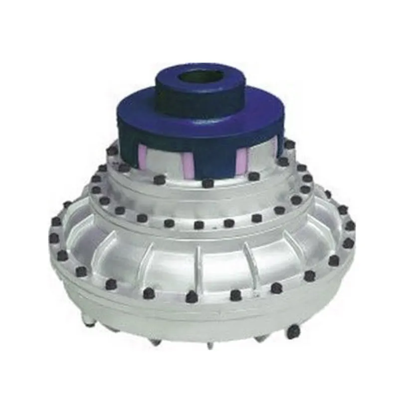
Fluid Coupling and Smooth Power Transmission during Starting and Stopping
A fluid coupling is designed to facilitate smooth power transmission during the starting and stopping phases of machinery and equipment. It achieves this by utilizing the principle of hydrodynamic torque transmission through a fluid medium.
Starting Phase: When power is initially supplied to the input shaft of the fluid coupling, the impeller (also known as the pump) begins to rotate, imparting energy to the fluid inside the coupling. As the fluid gains kinetic energy, it starts moving outward towards the turbine (also called the driven element) due to centrifugal force.
The kinetic energy of the moving fluid causes the turbine to start rotating, transmitting torque to the output shaft. During this starting phase, there is a slight time lag, known as the “slip,” between the impeller and the turbine. However, as the fluid coupling reaches its operational speed, the slip reduces, and the turbine matches the speed of the impeller, resulting in smooth power transmission from the input to the output shaft.
The fluid coupling’s ability to control the slip ensures a gradual and controlled acceleration of the driven equipment, minimizing stress on the drivetrain components and preventing sudden shock loads.
Stopping Phase: When power to the input shaft is reduced or cut off, the impeller slows down, and the kinetic energy in the fluid decreases. As a result, the fluid moves away from the turbine towards the center of the coupling, reducing the torque transmission between the input and output shafts.
This characteristic of the fluid coupling aids in smoothly decelerating the connected equipment, preventing sudden jolts or jerks during the stopping process. The ability to control the slip during deceleration ensures that the driven machinery comes to a gradual and controlled stop, enhancing safety and protecting the equipment from damage.
The combination of hydrodynamic torque transmission and the ability to control the slip makes fluid couplings ideal for applications where smooth power transmission during starting and stopping is essential. Industries such as mining, construction, metal processing, marine propulsion, and power generation benefit from the reliable and efficient performance of fluid couplings in various machinery and equipment.

Real-World Case Studies: Improved Performance with Fluid Couplings
Fluid couplings have been widely adopted in various industries, and numerous real-world case studies demonstrate their positive impact on performance and efficiency. Here are a few examples:
Case Study 1: Mining Conveyor System
In a large mining operation, a conveyor system used to transport heavy loads of ore experienced frequent starts and stops due to fluctuating material supply. The abrupt starting and stopping led to significant wear and tear on the conveyor components, causing frequent breakdowns and maintenance downtime.
After installing fluid couplings at critical points in the conveyor system, the soft start and stop capability of the fluid couplings significantly reduced the mechanical stress during operation. This led to a smoother material flow, reduced conveyor wear, and extended equipment life. Additionally, the fluid couplings’ overload protection feature prevented damage to the conveyor during peak loads, ensuring uninterrupted production.
Case Study 2: Marine Propulsion System
In a marine vessel equipped with traditional direct drive systems, the crew faced challenges in maneuvering the ship efficiently. The fixed propeller arrangement made it challenging to control the vessel’s speed and direction accurately, leading to increased fuel consumption and decreased maneuverability.
By retrofitting the vessel’s propulsion system with fluid couplings, the ship’s performance improved significantly. The fluid couplings allowed for flexible and smooth speed control, enabling precise maneuvering and reduced fuel consumption. The ability to adjust the load on the propeller enhanced the vessel’s overall efficiency, resulting in reduced operating costs and improved environmental sustainability.
Case Study 3: Industrial Pumping Station
In an industrial pumping station, the constant starting and stopping of the pumps caused water hammer and pressure surges within the pipeline network. The sudden hydraulic shocks led to pipe bursts, valve failures, and increased energy consumption.
After implementing fluid couplings in the pump drive systems, the pumps could be softly started and stopped. The fluid couplings’ torque control capabilities ensured a gradual increase in pump speed, eliminating water hammer and pressure surges. As a result, the pumping station’s reliability improved, maintenance costs decreased, and the energy consumption reduced due to smoother pump operations.
These case studies demonstrate the positive effects of using fluid couplings in various applications. They highlight how fluid couplings contribute to improved performance, reduced mechanical stress, enhanced control, and cost savings in industrial machinery and systems.
“`
Principle of Hydrodynamic Fluid Coupling
A hydrodynamic fluid coupling operates on the principle of hydrokinetics, utilizing hydraulic fluid to transmit power between an engine or prime mover and a driven load. The key components of a fluid coupling are the impeller, the turbine, and the housing filled with hydraulic fluid.
Here’s how the principle works:
- Impeller: The impeller is connected to the engine’s crankshaft and is responsible for driving the hydraulic fluid. As the impeller rotates, it creates a flow of fluid within the housing.
- Fluid Flow: The rotational motion of the impeller causes the fluid to move radially outward, towards the housing walls. This generates a high-velocity fluid flow in the housing.
- Turbine: The turbine is connected to the driven load, such as a transmission or machinery input shaft. As the fluid flows onto the blades of the turbine, it causes the turbine to rotate.
- Power Transmission: The kinetic energy of the high-velocity fluid is transferred to the turbine, resulting in the rotation of the driven load. The power transmission is achieved purely through the hydrodynamic effect of the fluid flow.
- Slip: In a fluid coupling, there is always a slight difference in speed (slip) between the impeller and the turbine. This slip is necessary to allow the fluid to accelerate from rest to the speed of the turbine. As a result, the output speed of the driven load is always slightly less than the input speed from the engine.
Hydrodynamic fluid couplings provide several advantages, such as smooth power transmission, overload protection, and torsional vibration dampening. However, they do not provide torque multiplication like torque converters do, making them more suitable for applications where precise speed matching is required.


editor by CX 2024-05-06