Product Description
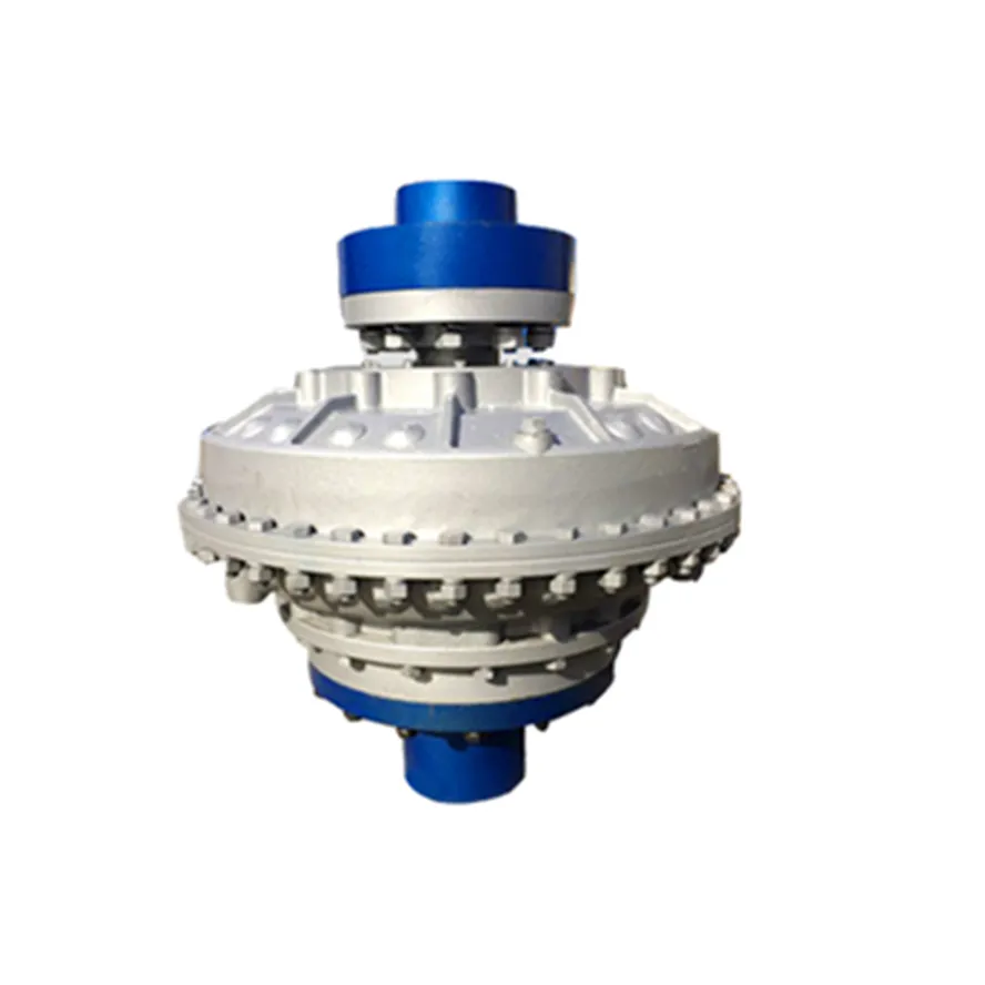
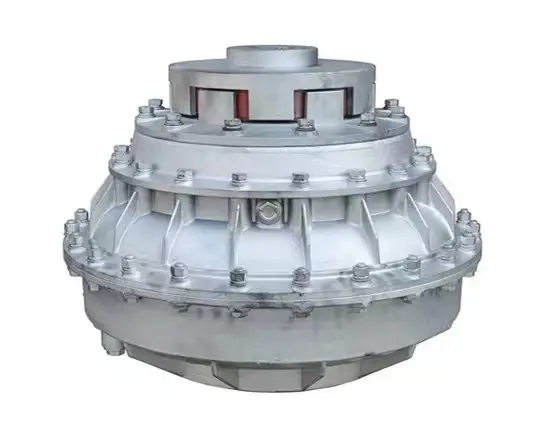
Diaphragm Coupling Shaft Coupling (JMI)
JM Series Diaphragm Coupling of flexible metal flexible coupling, which rely on the metal diaphragm to transmit torque from the main connection, motivation, has the advantages of elastic damping and no lubrication, no noise, is an ideal product for replacing the gear coupling and coupling current. It can compensate the axial, radial and angular deviation caused by the manufacturing error, installation error, bearing deformation and the change of temperature rise.
The main characteristics of JM Series Diaphragm Coupling:
1.Compensation 2 axis misalignment of the ability, and tooth type coupling can be much more than a double angle displacement, radial displacement of the small, flexible, allowing a certain axial, radial and angular displacement.
2. Obvious damping effect, no noise, no wear and tear.
3.High transmission efficiency, up to 99.86%. Especially suitable for medium and high speed high power transmission.
4.Adapt to high temperature (-80+300) and harsh environment, and can be in shock, vibration, safety and dynamic conditions.
5.Simple structure, light weight, small size, convenient assembly and disassembly. Without moving the machine can be disassembled (with intermediate type), no need of lubrication.
6.Accurately convey the rotational speed, the operation has not turned bad, can be used for the transmission of precision machinery.
JM series diaphragm flexible coupling is widely used in machinery and equipment industry, metallurgy, mines, petroleum, chemical, electric power, shipbuilding, lifting transport, textile, light industry, agricultural machinery, printing machinery and water pump, fan, etc. in the transmission of power machine.
|
||||||||||||||||||||||||||||||||||||||||||||||||||||||||||||||||||||||||||||||||||||||||||||||||||||||||||||||||||||||||||||||||||||||||||||||||||||||||||||||||||||||||||||||||||||||||||||||||||||||||||||||||||||||||||||||||||||||||||||||||||||||||||||||||||||||||||||||||||||||||||||||||||||||||||||||||||||||||||||||||||||||||||||||||||||||||||||||||||||||||||||||||||||||||
Detailed Photos
Company Profile
HangZhou CHINAMFG Machinery Manufacturing Co., Ltd. is a high-tech enterprise specializing in the design and manufacture of various types of coupling. There are 86 employees in our company, including 2 senior engineers and no fewer than 20 mechanical design and manufacture, heat treatment, welding, and other professionals.
Advanced and reasonable process, complete detection means. Our company actively introduces foreign advanced technology and equipment, on the basis of the condition, we make full use of the advantage and do more research and innovation. Strict to high quality and operate strictly in accordance with the ISO9000 quality certification system standard mode.
Our company supplies different kinds of products. High quality and reasonable price. We stick to the principle of “quality first, service first, continuous improvement and innovation to meet the customers” for the management and “zero defect, zero complaints” as the quality objective.
Our Services
1. Design Services
Our design team has experience in Cardan shafts relating to product design and development. If you have any needs for your new product or wish to make further improvements, we are here to offer our support.
2. Product Services
raw materials → Cutting → Forging →Rough machining →Shot blasting →Heat treatment →Testing →Fashioning →Cleaning→ Assembly→Packing→Shipping
3. Samples Procedure
We could develop the sample according to your requirement and amend the sample constantly to meet your need.
4. Research & Development
We usually research the new needs of the market and develop new models when there are new cars in the market.
5. Quality Control
Every step should be a particular test by Professional Staff according to the standard of ISO9001 and TS16949.
FAQ
Q 1: Are you a trading company or a manufacturer?
A: We are a professional manufacturer specializing in manufacturing
various series of couplings.
Q 2:Can you do OEM?
Yes, we can. We can do OEM & ODM for all customers with customized PDF or AI format artwork.
Q 3:How long is your delivery time?
Generally, it is 20-30 days if the goods are not in stock. It is according to quantity.
Q 4: Do you provide samples? Is it free or extra?
Yes, we could offer the sample but not for free. Actually, we have an excellent price principle, when you make the bulk order the cost of the sample will be deducted.
Q 5: How long is your warranty?
A: Our Warranty is 12 months under normal circumstances.
Q 6: What is the MOQ?
A: Usually our MOQ is 1pcs.
Q 7: Do you have inspection procedures for coupling?
A:100% self-inspection before packing.
Q 8: Can I have a visit to your factory before the order?
A: Sure, welcome to visit our factory.
Q 9: What’s your payment?
A:1) T/T.
♦Contact Us
Web: huadingcoupling
Add: No.11 HangZhou Road,Chengnan park,HangZhou City,ZheJiang Province,China
/* January 22, 2571 19:08:37 */!function(){function s(e,r){var a,o={};try{e&&e.split(“,”).forEach(function(e,t){e&&(a=e.match(/(.*?):(.*)$/))&&1

Can you explain the Concept of Slip in a Fluid Coupling?
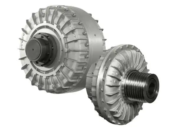
In a fluid coupling, slip refers to the relative speed difference between the impeller and the runner. When the impeller, which is connected to the driving shaft, rotates, it induces the flow of hydraulic fluid inside the coupling. This fluid flow in turn drives the rotation of the runner, which is connected to the driven shaft.
However, due to the operating principle of fluid couplings, there is always a certain amount of slip between the impeller and the runner. This slip occurs because the fluid coupling needs to allow for a small speed difference in order to transmit torque smoothly.
During startup or under heavy load conditions, the impeller’s rotational speed may be slightly higher than the runner’s rotational speed. This speed difference causes the hydraulic fluid to circulate between the impeller and the runner, generating hydrodynamic forces that transmit torque from the driving shaft to the driven shaft.
Slip is an inherent and controlled characteristic of fluid couplings, and it is essential for their smooth operation. However, excessive slip can lead to energy losses and reduced efficiency. Therefore, fluid couplings are designed to have an optimal slip value for specific applications, balancing the need for torque transmission and energy efficiency.

Real-World Case Studies: Improved Performance with Fluid Couplings
Fluid couplings have been widely adopted in various industries, and numerous real-world case studies demonstrate their positive impact on performance and efficiency. Here are a few examples:
Case Study 1: Mining Conveyor System
In a large mining operation, a conveyor system used to transport heavy loads of ore experienced frequent starts and stops due to fluctuating material supply. The abrupt starting and stopping led to significant wear and tear on the conveyor components, causing frequent breakdowns and maintenance downtime.
After installing fluid couplings at critical points in the conveyor system, the soft start and stop capability of the fluid couplings significantly reduced the mechanical stress during operation. This led to a smoother material flow, reduced conveyor wear, and extended equipment life. Additionally, the fluid couplings’ overload protection feature prevented damage to the conveyor during peak loads, ensuring uninterrupted production.
Case Study 2: Marine Propulsion System
In a marine vessel equipped with traditional direct drive systems, the crew faced challenges in maneuvering the ship efficiently. The fixed propeller arrangement made it challenging to control the vessel’s speed and direction accurately, leading to increased fuel consumption and decreased maneuverability.
By retrofitting the vessel’s propulsion system with fluid couplings, the ship’s performance improved significantly. The fluid couplings allowed for flexible and smooth speed control, enabling precise maneuvering and reduced fuel consumption. The ability to adjust the load on the propeller enhanced the vessel’s overall efficiency, resulting in reduced operating costs and improved environmental sustainability.
Case Study 3: Industrial Pumping Station
In an industrial pumping station, the constant starting and stopping of the pumps caused water hammer and pressure surges within the pipeline network. The sudden hydraulic shocks led to pipe bursts, valve failures, and increased energy consumption.
After implementing fluid couplings in the pump drive systems, the pumps could be softly started and stopped. The fluid couplings’ torque control capabilities ensured a gradual increase in pump speed, eliminating water hammer and pressure surges. As a result, the pumping station’s reliability improved, maintenance costs decreased, and the energy consumption reduced due to smoother pump operations.
These case studies demonstrate the positive effects of using fluid couplings in various applications. They highlight how fluid couplings contribute to improved performance, reduced mechanical stress, enhanced control, and cost savings in industrial machinery and systems.
“`
Comparison: Fluid Coupling vs. Torque Converter
Fluid couplings and torque converters are both hydrodynamic devices used in automotive and industrial applications to transmit power between an engine and a driven load. While they share some similarities, they also have distinct differences:
- Function: The primary function of both fluid couplings and torque converters is to transmit rotational power from the engine to the transmission or driven load. They allow for smooth power transmission and provide a degree of isolation between the engine and the load.
- Construction: Both devices consist of an impeller, a turbine, and a housing filled with hydraulic fluid (usually oil). The impeller is connected to the engine’s crankshaft, the turbine to the transmission/input shaft, and the housing is shared between the two.
- Torque Transmission: In a fluid coupling, the power is transmitted purely through hydrodynamic principles. The impeller accelerates the fluid, which then drives the turbine. However, there is no torque multiplication, and the output speed is always slightly less than the input speed. On the other hand, a torque converter can provide torque multiplication due to its stator, which redirects the fluid flow and increases the torque transmitted to the turbine.
- Lock-up Clutch: Some torque converters have a lock-up clutch that can mechanically connect the impeller and the turbine at higher speeds. This effectively eliminates the slip between the two elements and increases overall efficiency, similar to the operation of a fluid coupling at higher speeds.
- Automotive Use: Torque converters are commonly used in automatic transmissions in vehicles, while fluid couplings were more prevalent in older manual transmissions. However, modern manual transmissions generally use clutch systems instead of fluid couplings.
- Efficiency: Fluid couplings are generally more efficient than torque converters, especially at higher speeds. Torque converters can experience efficiency losses due to fluid slippage and the operation of the stator.
- Applications: Fluid couplings find applications in various industrial machinery, such as conveyors, pumps, and crushers, where the priority is smooth power transmission and overload protection. Torque converters are primarily used in vehicles, offering the benefit of automatic gear shifting and torque multiplication during acceleration.
Overall, both fluid couplings and torque converters play essential roles in power transmission, but their specific design and application characteristics determine their suitability for different use cases.


editor by CX 2024-05-07