Product Description
Flexible Shaft Chain Coupling Rigid Bellow Grid Beam Tyre Roller Fluid Jaw Compliant Mechanism Oldham Coupler Rag Joint Universal Joint Dis Motor HRC Coupling
A flexible shaft chain coupling connects 2 shafts in a rotating system. It is designed to provide a loose connection between the shafts, allowing for misalignment or axial movement.
The flexible shaft chain coupling consists of 2 hubs connected by a chain or series of links. The hubs are typically made from steel or aluminum and are designed to fit CHINAMFG the shafts to be connected. The chain or links provide the flexibility to accommodate misalignment or axial movement between the posts.
Flexible shaft chain couplings are commonly used in applications with misalignment or axial movement between the shafts, such as pumps, compressors, or generators. They can also help absorb shock and vibration in the system, which can help protect the equipment and reduce maintenance costs.
One of the advantages of flexible shaft chain couplings is their ability to transmit torque between the 2 shafts while allowing for some misalignment or axial movement. They are also relatively easy to install and maintain and can be used in various industrial applications.
A flexible shaft chain coupling provides a flexible and reliable way to connect 2 shafts in a rotating system. Accommodating misalignment and axial movement can help reduce wear and tear on the equipment and improve overall system efficiency and reliability.
/* January 22, 2571 19:08:37 */!function(){function s(e,r){var a,o={};try{e&&e.split(“,”).forEach(function(e,t){e&&(a=e.match(/(.*?):(.*)$/))&&1

Handling Overloads and Stall Conditions in Fluid Couplings
A fluid coupling is designed to handle overloads and stall conditions in power transmission systems. When an overload or stall occurs, the fluid coupling utilizes its unique operating principle to protect the drivetrain and the connected machinery:
- Slip Feature: One of the key characteristics of a fluid coupling is its ability to slip at high torque loads. When an overload situation arises, the fluid coupling allows some relative motion between the input and output sides, known as slip. This slip absorbs the excess torque and prevents it from being transferred to the driven equipment, effectively protecting it from damage.
- Fluid Circulation: During normal operation, the fluid inside the coupling circulates smoothly between the impeller and turbine, transmitting torque with minimal losses. However, when an overload or stall condition occurs, the fluid circulation may become turbulent, generating heat in the process. This heat dissipation helps in absorbing and dissipating the excess energy, preventing the transmission system from experiencing sudden stress.
- Automatic Reconnection: After an overload or stall condition, once the excess torque is dissipated through slip and heat, the fluid coupling automatically reconnects the input and output sides, resuming the power transmission. This automatic reconnection ensures that the system returns to normal operation once the overload situation is resolved.
- Sturdy Construction: Fluid couplings are designed with robust and durable materials to withstand high torque and thermal stresses during overload conditions. The strong construction ensures that the fluid coupling remains reliable and operational even after multiple overload events.
Overall, a fluid coupling’s ability to handle overloads and stall conditions makes it a reliable and essential component in various industrial applications. By providing overload protection and slip characteristics, fluid couplings help prevent costly damage to equipment, increase operational safety, and contribute to the longevity of the entire power transmission system.

Special Considerations for Using Fluid Couplings in Explosive Environments
Fluid couplings are widely used in various industrial applications, including those in potentially explosive environments. When considering the use of fluid couplings in such settings, several special considerations must be taken into account to ensure safety and compliance with regulations:
- Explosion-Proof Design: Fluid couplings used in explosive environments must be designed to prevent the ignition of flammable gases or vapors. They should adhere to explosion-proof standards and be equipped with robust seals and protective enclosures to contain any potential sparks or flames.
- Ingress Protection: An appropriate ingress protection (IP) rating is essential to prevent dust, moisture, or other hazardous substances from entering the fluid coupling. A higher IP rating ensures greater protection against potential sources of ignition.
- Material Selection: The choice of materials for the fluid coupling is crucial in explosive environments. Non-sparking or anti-static materials should be used to reduce the risk of ignition caused by friction or electrical discharge.
- Temperature Limitations: Fluid couplings operating in explosive environments must have temperature ratings that prevent overheating and potential ignition of flammable substances. The fluid coupling should be adequately cooled to maintain safe operating temperatures.
- Monitoring and Maintenance: Regular monitoring and maintenance of fluid couplings in explosive environments are essential. Periodic inspections can detect potential issues or wear that could compromise the safety of the coupling. Any maintenance or repair work should be carried out by qualified personnel following safety protocols.
- Compliance with Regulations: Depending on the industry and location, there may be specific regulations and safety standards that govern the use of equipment in explosive atmospheres. It is crucial to adhere to these regulations and ensure that the fluid coupling complies with all relevant safety requirements.
Fluid couplings used in explosive environments play a vital role in ensuring the safe and reliable operation of industrial machinery. By providing smooth and controlled power transmission, fluid couplings can help minimize risks and improve the overall safety of the equipment and personnel in these hazardous settings.
Before implementing fluid couplings in explosive environments, it is essential to conduct a thorough risk assessment and consult with experts familiar with the specific safety requirements of the industry. By taking appropriate safety measures and selecting suitable explosion-proof fluid couplings, the risks associated with using power transmission equipment in hazardous areas can be effectively mitigated.

Maintenance Practices for Fluid Couplings
Regular maintenance is crucial to keep a fluid coupling in good condition and ensure its longevity. Here are the key maintenance practices:
- Fluid Level Checks: Regularly inspect the fluid level in the fluid coupling. Maintain the fluid level within the recommended range specified by the manufacturer.
- Fluid Quality: Monitor the quality of the fluid in the fluid coupling. Check for any signs of contamination, degradation, or discoloration. If the fluid shows signs of wear, replace it following the manufacturer’s guidelines.
- Fluid Replacement: As part of routine maintenance, consider replacing the fluid periodically, even if there are no visible signs of wear. Fluid replacement intervals may vary based on the application and operating conditions.
- Lubrication: Ensure proper lubrication of the fluid coupling components, including bearings and seals, as specified by the manufacturer.
- Inspections: Regularly inspect the fluid coupling for any signs of leaks, damage, or unusual noises during operation. Address any issues promptly to prevent further damage.
- Alignment: Verify that the fluid coupling is correctly aligned with the connected equipment. Misalignment can lead to premature wear and reduced performance.
- Coupling Bolts: Check and tighten the coupling bolts as needed to maintain proper coupling integrity.
- Temperature Monitoring: Monitor the operating temperature of the fluid coupling. Elevated temperatures may indicate an issue that needs attention.
- Vibration Analysis: Periodically perform vibration analysis to detect any abnormal vibrations that could indicate potential problems.
- Manufacturer Guidelines: Follow the maintenance guidelines and recommendations provided by the fluid coupling manufacturer.
By adhering to these maintenance practices, you can extend the life of your fluid coupling, improve its reliability, and minimize the risk of unexpected failures.


editor by CX 2024-05-07
China Best Sales Drive Pipe Spline Shaft Disc Flange Gear Rubber Jaw Motor Spacer Beam Rigid Fluid Chain Nm Mh HRC Pin Fenaflex Spacer Elastomeric Flexible Gear Coupling
Product Description
Drive Pipe Spline Shaft Disc Flange Gear Rubber Jaw Motor Spacer Beam Rigid Fluid Chain Nm Mh HRC Pin Fenaflex Spacer Elastomeric flexible gear Coupling
Application of Shaft Chain Coupling
A shaft chain coupling is a type of coupling that is used to connect 2 shafts that are not perfectly aligned. The coupling consists of a chain that is connected to 2 sprockets, 1 on each shaft. The chain allows the shafts to move slightly relative to each other, which helps to compensate for misalignment.
Shaft chain couplings are used in a wide variety of applications, including:
- Conveyors: Shaft chain couplings are used in conveyors to transmit power from the motor to the conveyor belt.
- Pumps: Shaft chain couplings are used in pumps to transmit power from the motor to the pump shaft.
- Fans: Shaft chain couplings are used in fans to transmit power from the motor to the fan shaft.
- Generators: Shaft chain couplings are used in generators to transmit power from the turbine to the generator rotor.
- Wind turbines: Shaft chain couplings are used in wind turbines to transmit power from the turbine to the generator rotor.
Shaft chain couplings are a versatile and reliable type of coupling that can be used in a wide variety of applications. They offer a number of advantages over other types of couplings, including:
- Can compensate for misalignment: Shaft chain couplings can compensate for misalignment up to 2 degrees. This makes them ideal for applications where the shafts are not perfectly aligned, such as when the equipment is installed in a new location or when the equipment is subject to vibration.
- Easy to install: Shaft chain couplings are easy to install and maintain. They can be installed without special tools or training.
- Available in a variety of sizes and styles: Shaft chain couplings are available in a variety of sizes and styles to meet the needs of different applications. This makes it easy to find a coupling that is the right size and style for your application.
- Highly efficient: Shaft chain couplings are highly efficient, meaning that they transmit a large percentage of the power from the driving shaft to the driven shaft. This can save money on energy costs.
- Durable: Shaft chain couplings are durable and can withstand a wide range of operating conditions.
Here are some of the disadvantages of using shaft chain couplings:
- Cost: Shaft chain couplings can be more expensive than other types of couplings.
- Maintenance: Shaft chain couplings require periodic maintenance, such as checking the coupling for wear and tear and lubricating the chain as needed.
Overall, shaft chain couplings are a versatile and reliable type of coupling that can be used in a wide variety of applications. They offer a number of advantages over other types of couplings, but they also have some disadvantages. The best type of coupling for a particular application will depend on the specific requirements of that application.
Fluid Couplings in Wind Turbines for Power Generation
Yes, fluid couplings can be used in wind turbines for power generation, and they play a significant role in optimizing the performance and efficiency of the turbine system. In a wind turbine, the fluid coupling is typically installed between the rotor hub and the main gearbox.
Here’s how fluid couplings are beneficial in wind turbines:
- Soft Start and Load Distribution: During the startup phase, the wind turbine experiences varying wind speeds, and a fluid coupling allows for a smooth soft start by gradually transferring torque from the rotor to the gearbox. This reduces mechanical stress on the components and prevents sudden load shocks.
- Torque Limiting: In high wind conditions, when the wind speed exceeds the rated limit, the fluid coupling can slip, decoupling the rotor from the gearbox. This torque limiting feature protects the gearbox and other drivetrain components from overloading and potential damage.
- Torsional Vibration Damping: Wind turbines are subject to dynamic loads and torsional vibrations due to wind gusts. The fluid coupling acts as a torsional damper, damping these vibrations and ensuring smoother and stable operation of the system.
- Overload Protection: If there is a sudden increase in wind speed, causing an overload condition, the fluid coupling helps absorb the excess torque and protects the turbine from overloading.
- Contamination Prevention: Wind turbine environments are often exposed to dust, dirt, and moisture. The fluid coupling provides an enclosed and sealed environment for the drivetrain, preventing contaminants from entering and extending the life of internal components.
- Redundancy: Some wind turbine designs employ multiple drivetrain stages, including redundant fluid couplings. This redundancy can enhance the reliability and safety of the turbine by providing backup systems in case of component failures.
- Energy Efficiency: By facilitating smooth start-ups and load distribution, fluid couplings contribute to the overall energy efficiency of the wind turbine system. This allows the turbine to harness wind energy more effectively and generate electricity efficiently.
Incorporating fluid couplings in wind turbines helps improve their overall performance, reliability, and lifespan while reducing maintenance requirements and operating costs. As a result, they are commonly used in modern wind turbine designs to optimize power generation from renewable wind resources.

Safety Features in Modern Fluid Coupling Designs
Modern fluid coupling designs incorporate various safety features to ensure the reliable and secure operation of the equipment. Here are some of the key safety features commonly found in modern fluid couplings:
1. Overload Protection: One of the primary safety features in modern fluid couplings is overload protection. In the event of an abrupt increase in load or torque, the fluid coupling slips, absorbing the excess torque and preventing damage to the connected equipment. This feature safeguards against mechanical failures and protects the machinery.
2. Torque Limiting: Fluid couplings are designed with torque limiting capabilities, which allow them to control the maximum torque transmitted to the driven equipment. By setting the torque limit within a safe operating range, the fluid coupling prevents excessive stresses on the system, ensuring longevity and reliability.
3. Automatic Overheat Protection: Some fluid couplings are equipped with automatic overheat protection mechanisms. If the fluid coupling’s operating temperature exceeds a predefined threshold, the protection system disengages the coupling temporarily until the temperature returns to a safe level. This prevents damage due to overheating and enhances safety.
4. Backstop or Holdback Device: In certain applications where reverse rotation is a concern, fluid couplings may include a backstop or holdback device. This feature prevents the driven equipment from rotating in the opposite direction, enhancing safety during sudden stops or reversals.
5. Fail-Safe Operation: Many modern fluid couplings are designed to operate in a fail-safe manner. In the event of any malfunction or failure, the coupling defaults to a safe mode, allowing the equipment to continue operating at reduced capacity or gradually shut down, avoiding catastrophic failures.
6. Seal Protection: Proper sealing is crucial for fluid couplings, especially in harsh environments. Modern designs often include advanced seal protection features to prevent oil leakage and contamination, ensuring environmental safety and reducing maintenance requirements.
7. Low Noise and Vibration: Reduced noise and vibration levels in fluid couplings contribute to operator safety and comfort. The damping properties of the fluid coupling help minimize vibrations, creating a quieter and more stable working environment.
8. Emergency Stop Capability: Some fluid couplings may have emergency stop provisions to quickly disengage the coupling in critical situations. This feature allows for rapid shutdowns in emergencies, preventing accidents and protecting personnel.
9. Condition Monitoring: Advanced fluid coupling designs may include condition monitoring capabilities. This allows operators to monitor the coupling’s performance, temperature, and other parameters in real-time, facilitating predictive maintenance and avoiding unexpected failures.
Overall, the incorporation of these safety features in modern fluid coupling designs ensures the protection of machinery, operators, and the surrounding environment. These safety measures enhance the reliability, efficiency, and longevity of equipment, making fluid couplings a safe and valuable choice for power transmission in various industrial applications.
Disadvantages and Limitations of Fluid Couplings
While fluid couplings offer numerous advantages, they also have some disadvantages and limitations that should be considered for specific applications:
- Power Loss: Fluid couplings introduce a power loss due to the slip that occurs during power transmission. This power loss can reduce the overall efficiency of the system, especially in applications with high-speed variations.
- Torque Multiplication: Unlike torque converters, fluid couplings have limited torque multiplication capabilities. They do not provide as much torque increase at low speeds, which may be necessary for certain heavy-load applications.
- Temperature Sensitivity: Fluid couplings are sensitive to temperature changes. In extremely hot or cold conditions, the viscosity of the fluid may vary, affecting the coupling’s performance.
- Fluid Contamination: Contaminants in the fluid can adversely affect the performance and lifespan of the fluid coupling. Regular maintenance and monitoring of the fluid quality are essential to prevent potential issues.
- Speed Limitations: Fluid couplings may have speed limitations in certain applications. High-speed operations can lead to centrifugal forces that may affect the coupling’s behavior.
- Complexity in Control: In some cases, controlling the output speed of the fluid coupling can be more challenging compared to other types of couplings. This complexity may require additional control mechanisms.
- Cost: Fluid couplings can be more expensive than some mechanical couplings, such as belt and chain drives. The initial cost and ongoing maintenance expenses should be considered in the selection process.
Despite these limitations, fluid couplings remain a popular choice in many industrial applications, thanks to their smooth power transmission, overload protection, and torsional vibration damping capabilities. The decision to use a fluid coupling should be based on a thorough understanding of the specific requirements and operating conditions of the machinery or equipment.
editor by CX 2023-10-09
China high quality Flexible Shaft Chain Coupling Rigid Bellow Grid Beam Tyre Roller Fluid Jaw Compliant Mechanism Oldham Coupler Rag Joint Universal Joint Dis Motor HRC Coupling
Product Description
Flexible Shaft Chain Coupling Rigid Bellow Grid Beam Tyre Roller Fluid Jaw Compliant Mechanism Oldham Coupler Rag Joint Universal Joint Dis Motor HRC Coupling
A flexible shaft chain coupling connects 2 shafts in a rotating system. It is designed to provide a loose connection between the shafts, allowing for misalignment or axial movement.
The flexible shaft chain coupling consists of 2 hubs connected by a chain or series of links. The hubs are typically made from steel or aluminum and are designed to fit CHINAMFG the shafts to be connected. The chain or links provide the flexibility to accommodate misalignment or axial movement between the posts.
Flexible shaft chain couplings are commonly used in applications with misalignment or axial movement between the shafts, such as pumps, compressors, or generators. They can also help absorb shock and vibration in the system, which can help protect the equipment and reduce maintenance costs.
One of the advantages of flexible shaft chain couplings is their ability to transmit torque between the 2 shafts while allowing for some misalignment or axial movement. They are also relatively easy to install and maintain and can be used in various industrial applications.
A flexible shaft chain coupling provides a flexible and reliable way to connect 2 shafts in a rotating system. Accommodating misalignment and axial movement can help reduce wear and tear on the equipment and improve overall system efficiency and reliability.
Key Parameters in Designing a Fluid Coupling System
Designing a fluid coupling system requires careful consideration of various parameters to ensure optimal performance and efficiency. Here are the key parameters to take into account:
- Power Rating: Determine the power requirements of the connected equipment to select a fluid coupling with an appropriate power rating. Undersized couplings may lead to overheating and premature wear, while oversized couplings can result in energy losses.
- Input and Output Speeds: Consider the rotational speeds of the input and output shafts to ensure the fluid coupling can accommodate the desired speed range without slipping or exceeding its limitations.
- Torque Capacity: Calculate the maximum torque expected in the system and choose a fluid coupling with a torque capacity that exceeds this value to handle occasional overloads and prevent damage.
- Fluid Viscosity: The viscosity of the fluid inside the coupling affects its torque transmission capabilities. Select a fluid viscosity suitable for the application and operating conditions.
- Start-Up and Load Conditions: Analyze the start-up torque and load variations during operation. The fluid coupling should be capable of handling these conditions without excessive slip or stress on the drivetrain.
- Environmental Factors: Consider the ambient temperature, humidity, and potential exposure to contaminants. Ensure the fluid coupling’s materials and sealing mechanisms can withstand the environmental conditions.
- Size and Weight: Optimize the size and weight of the fluid coupling to minimize space requirements and facilitate installation and maintenance.
- Torsional Resonance: Evaluate torsional resonances in the system and select a fluid coupling with appropriate damping characteristics to mitigate vibrations.
- Overload Protection: Determine if overload protection features, such as slip or torque limiting, are necessary to safeguard the connected equipment from damage.
- Compatibility: Ensure the fluid coupling is compatible with the specific application, including the type of driven equipment, its mechanical characteristics, and any other interrelated components in the drivetrain.
- Operational Costs: Consider the long-term operational costs, maintenance requirements, and efficiency of the fluid coupling to optimize the overall lifecycle cost of the system.
- Safety Standards: Adhere to relevant safety standards and regulations in the design and installation of the fluid coupling system to ensure safe and reliable operation.
By carefully evaluating these parameters and selecting a fluid coupling that aligns with the specific requirements of the application, engineers can design a reliable and efficient fluid coupling system for various industrial and power transmission applications.
Contribution of Fluid Coupling to the Overall Efficiency of a Mechanical System
A fluid coupling plays a crucial role in improving the overall efficiency of a mechanical system, especially in applications where smooth power transmission, soft-starting, and torque control are essential. Here’s how a fluid coupling contributes to system efficiency:
1. Smooth Power Transmission:
Fluid couplings provide a smooth and gradual transfer of power from the driving to the driven machinery. The absence of direct mechanical contact between the input and output shafts reduces shock loads and vibrations, leading to less wear and tear on the connected equipment. This smooth power transmission results in increased system efficiency and reduced downtime.
2. Soft-Start Capability:
Fluid couplings offer soft-starting functionality, which is particularly beneficial for high-inertia or heavy-load applications. During startup, the fluid coupling allows the input shaft to gradually accelerate the output shaft, preventing sudden jerks or torque spikes. Soft-starting not only protects the mechanical components but also reduces energy consumption during the starting phase, contributing to overall efficiency.
3. Torque Control:
Fluid couplings enable precise control over the torque transmitted between the driving and driven machinery. By adjusting the fill level or using variable speed couplings, the torque output can be fine-tuned to match the requirements of the application. This feature ensures optimal performance and energy efficiency, especially in systems where torque demand varies during operation.
4. Overload Protection:
In case of sudden overloads or jamming of the driven machinery, the fluid coupling acts as a torque limiter. It will slip and absorb excess torque, protecting the mechanical system from damage. This overload protection not only safeguards the equipment but also contributes to the longevity and efficiency of the entire system.
5. Heat Dissipation:
Fluid couplings can absorb and dissipate heat generated during continuous operations. This heat dissipation capability prevents the system from overheating, ensuring consistent performance and avoiding thermal damage to the machinery. By maintaining proper operating temperatures, the fluid coupling aids in improving overall efficiency.
6. Energy Savings:
With its ability to reduce shock loads and provide smooth acceleration, a fluid coupling can help save energy during starting and stopping cycles. The elimination of mechanical shocks and vibrations reduces energy losses, resulting in higher overall energy efficiency.
In summary, a fluid coupling enhances the overall efficiency of a mechanical system by providing smooth power transmission, soft-start capability, precise torque control, overload protection, heat dissipation, and energy savings. Its contributions to reduced wear and tear, energy-efficient operations, and enhanced equipment lifespan make it a valuable component in various industrial applications.
Applications of Fluid Couplings in Industrial Machinery
Fluid couplings are widely used in various industrial machinery and equipment due to their unique characteristics and benefits. Some common applications include:
- Conveyors: Fluid couplings are used in conveyor systems to provide smooth start-ups and overload protection. They help in preventing damage to the conveyor belts and equipment during sudden starts and stops.
- Pumps: Fluid couplings are employed in pumps to control the acceleration and deceleration of the pump impeller. This ensures a gradual and controlled flow of fluids, reducing water hammer and pressure surges.
- Fans: Industrial fans often use fluid couplings to regulate fan speed and avoid abrupt changes in airflow, which can cause mechanical stress and system instability.
- Mining Equipment: Fluid couplings are used in mining machinery, such as crushers and conveyors, to protect the drivetrain from shock loads and to enhance equipment reliability.
- Marine Propulsion Systems: In marine applications, fluid couplings are used in propulsion systems to provide smooth engagement of the propeller, protecting the engine and transmission.
- Power Plants: Fluid couplings are utilized in power plants for boiler feed pumps, induced draft fans, and other equipment to achieve smooth operation and prevent sudden stress on mechanical components.
- Steel Industry: In steel mills, fluid couplings are employed in various equipment, including rolling mills and continuous casting machines, to protect the machinery and enhance productivity.
- Automotive: Fluid couplings are used in automatic transmissions to smoothly transmit power from the engine to the wheels, allowing smooth gear changes and preventing driveline shock.
- Wood Processing: In wood processing equipment, such as chippers and saws, fluid couplings are used to protect the equipment from shock loads and to achieve efficient power transmission.
Overall, fluid couplings play a crucial role in a wide range of industrial machinery applications, providing enhanced protection, smoother operation, and increased equipment longevity.
editor by CX 2023-10-08
China factory Hydrodynamic Jaw Rigid Beam Engine Shaft Motor Stainless Steel Torque Amplifier Torque Converter Water Brake Clutch Variable Speed Fluid Coupling
Product Description
hydrodynamic Jaw Rigid beam Engine Shaft Motor stainless Steel Torque amplifier Torque converter Water brake clutch variable speed fluid Coupling
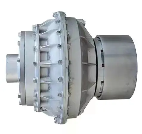
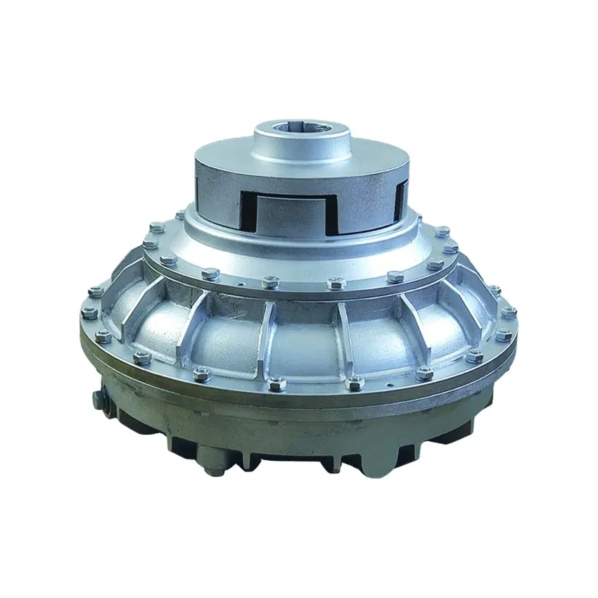
Application of fluid Coupling
A fluid coupling, also known as a hydraulic coupling, is a hydrodynamic or ‘hydrokinetic’ device used to transmit rotating mechanical power. It has been used in automobile transmissions as an alternative to a mechanical clutch. It also has widespread application in marine and industrial machine drives, where variable speed operation and controlled start-up without shock loading of the power transmission system is essential.
Applications of fluid couplings
Fluid couplings are used in a wide variety of applications, including:
- Automotive: Fluid couplings are used in automobiles to transmit power from the engine to the wheels. They also used in electric vehicles to control the speed of the electric motor.
- Machine tools: Fluid couplings are used in machine tools to transmit power from the motor to the cutting tool. This allows the cutting tool to operate at a high speed and torque, which is necessary for cutting through tough materials.
- Wind turbines: Fluid couplings are used in wind turbines to transmit power from the blades to the generator. This allows the generator to generate electricity at a controlled speed and torque, which is necessary for providing power to homes and businesses.
- Robotics: Fluid couplings are used in robotics to transmit power from the motor to the robot’s joints. This allows the robot to move its joints at a controlled speed and torque, which is necessary for performing tasks such as picking and placing objects.
- Conveyors: Fluid couplings are used in conveyors to transmit power from the motor to the conveyor belt. This allows the conveyor belt to move at a controlled speed and torque.
- Mining: Fluid couplings are used in mining equipment, such as crushers, conveyors, and pumps. The coupling allows the equipment to move materials at a controlled speed and torque, which is necessary for mining operations.
- Construction: Fluid couplings are used in construction equipment, such as excavators, cranes, and loaders. The coupling allows the machinery to move at a controlled speed and torque, which is necessary for construction operations.
- Aerospace: Fluid couplings are used in aerospace applications, such as jet engines and helicopters. The coupling allows the engines to operate at a controlled speed and torque, which is necessary for flight.
Advantages of fluid couplings
Fluid couplings offer a number of advantages over other types of couplings, including:
- Smooth start-up: Fluid couplings allow for a smooth start-up of the driven machine, without the shock loads that can be caused by other types of couplings.
- Variable speed operation: Fluid couplings can be used to vary the speed of the driven machine, without the need for a separate speed control device.
- Shock absorption: Fluid couplings can absorb shock loads, which can protect the driven machine from damage.
- Efficiency: Fluid couplings are very efficient, with losses typically less than 5%.
- Durability: Fluid couplings are very durable and can withstand a wide range of operating conditions.
Disadvantages of fluid couplings
Fluid couplings also have a few disadvantages, including:
- Cost: Fluid couplings can be more expensive than other types of couplings.
- Size and weight: Fluid couplings can be larger and heavier than other types of couplings.
- Maintenance: Fluid couplings require regular maintenance, such as checking the fluid level and replacing the filter.
Overall, fluid couplings are a versatile and valuable tool for a variety of applications. They offer a number of advantages over other types of couplings, including smooth start-up, variable speed operation, shock absorption, efficiency, and durability. However, they can be more expensive and require more maintenance than other types of couplings.

Fluid Couplings in Marine Propulsion Systems
Yes, fluid couplings can be and are commonly used in marine propulsion systems. They offer several advantages that make them well-suited for such applications:
- Smooth Power Transmission: Fluid couplings provide smooth power transmission, which is beneficial for marine propulsion where abrupt changes in power delivery can be detrimental to the vessel’s stability and performance.
- Torque Limiting: In marine applications, fluid couplings can act as torque limiters, protecting the propulsion system and engine from sudden torque surges and overloads, which can occur during maneuvers or when encountering resistance in water.
- Impact Damping: The hydrodynamic principle of fluid couplings helps dampen impacts and shocks in the propulsion system, reducing wear and tear on the components and extending their lifespan.
- Load Sharing: In multi-engine marine setups, fluid couplings facilitate load sharing between engines, ensuring each engine contributes its share of power to achieve optimal propulsion efficiency.
- Start-up Performance: Fluid couplings enable controlled and gradual acceleration during start-up, which is crucial for large vessels and applications where sudden torque spikes could damage the drivetrain or disturb the vessel’s balance.
- Overload Protection: The fluid coupling’s ability to slip at high loads provides inherent overload protection to the marine propulsion system, safeguarding it against potential damage.
Fluid couplings used in marine applications are specially designed to withstand the harsh conditions of the marine environment, including exposure to saltwater, humidity, and vibration. They are available in various sizes and configurations to accommodate different marine vessel types and power requirements.
Overall, fluid couplings offer reliable and efficient power transmission solutions for marine propulsion systems, contributing to the safe and smooth operation of the vessel.

Fluid Couplings in High-Temperature Environments
Fluid couplings are versatile power transmission devices commonly used in various industrial applications. However, their suitability for high-temperature environments depends on several factors, including the design, materials, and the specific operating conditions.
Here are some key considerations regarding the use of fluid couplings in high-temperature environments:
- Fluid Type: The type of fluid used inside the coupling greatly influences its temperature capabilities. Some fluid couplings are designed to handle higher temperatures by using specially formulated high-temperature fluids that can withstand elevated heat levels without degradation.
- Materials: The materials used in the construction of the fluid coupling play a crucial role in determining its maximum temperature tolerance. High-quality materials with good heat resistance properties are required to ensure reliable performance in high-temperature conditions.
- Lubrication: Proper lubrication is essential to reduce friction and heat generation within the fluid coupling. In high-temperature environments, ensuring sufficient and appropriate lubrication is crucial to prevent excessive wear and potential damage.
- Cooling: Some fluid couplings come equipped with cooling systems, such as cooling fins or external cooling circuits, to dissipate excess heat generated during operation. These cooling mechanisms can enhance the coupling’s capacity to handle higher temperatures.
- Application Considerations: The specific application and load requirements must be taken into account. In some cases, high-temperature conditions may be intermittent or occasional, allowing the fluid coupling to cool down between cycles. However, continuous high-temperature operation may require a more robust and specialized fluid coupling.
It is important to consult with the fluid coupling manufacturer to understand the temperature limitations and performance capabilities of their products. Manufacturers can provide guidance on selecting the appropriate fluid coupling for specific high-temperature applications.
While fluid couplings can be suitable for moderate to high-temperature environments, it is essential to operate them within their specified temperature range to ensure optimal performance and longevity. Extreme temperatures beyond the coupling’s rated limits can lead to accelerated wear, reduced efficiency, and potential damage, ultimately affecting the reliability of the power transmission system.
In summary, fluid couplings can be used in high-temperature environments, provided that the coupling’s design, materials, and lubrication are suitable for the specific application and operating conditions. Regular maintenance and adherence to the manufacturer’s guidelines are essential to ensure reliable performance and durability in such environments.

Examples of Industries Using Fluid Couplings
Fluid couplings find applications in various industries where smooth power transmission and torque control are required. Some common industries that commonly use fluid couplings include:
- Mining: Fluid couplings are used in mining equipment such as conveyors, crushers, and excavators to provide controlled startup and overload protection.
- Construction: Construction machinery like cranes, loaders, and piling rigs use fluid couplings for efficient power transmission and reduced shock loads.
- Marine: Fluid couplings are employed in marine propulsion systems to optimize engine performance and protect against sudden load changes.
- Steel and Metal Processing: Industries dealing with metal processing use fluid couplings in rolling mills, coilers, and metal forming machines for soft start and overload protection.
- Pulp and Paper: Pulp and paper mills utilize fluid couplings in various equipment, such as chippers, conveyors, and pumps, for smooth power transmission.
- Automotive: In automotive applications, fluid couplings can be found in torque converters, which provide smooth torque transmission in automatic transmissions.
- Energy and Power Generation: Fluid couplings are used in power plants for applications like fans, pumps, and turbines to control power transmission and reduce mechanical stress during startup.
- Wastewater Treatment: Fluid couplings are used in wastewater treatment plants for applications like aerators and pumps, ensuring efficient power transmission and equipment protection.
- Food and Beverage: Industries dealing with food processing and beverage production use fluid couplings in various applications to ensure gentle power transmission and prevent sudden load shocks.
- Chemical and Petrochemical: Fluid couplings are used in pumps and mixers in chemical and petrochemical processing to control torque and protect equipment.
These examples illustrate the versatility of fluid couplings and their widespread use across diverse industries to enhance the efficiency and safety of power transmission systems.
editor by CX 2023-09-11
China Stainless Steel Heart Butterfly Couple Bracelets for Mommy Grandma Sister Generation Friendship Fashion Jewelry Card Bracelet coupling beam
Product Amount: Make a Desire Bracelets with Information Card
Jewelry Primary Materials: Stainless Steel
Content Sort: Stainless Steel
Diamond shape: Stainless Steel
Pearl Kind: Stainless Metal
Bracelets or Bangles Type: Attraction Bracelets
Gender: Children’s, Men’s, Unisex, Women’s
Main Stone: Stainless Metal
Jewelry Variety: Bracelets, Bangles
Event: Anniversary, Engagement, Present, Get together, Marriage, Christmas, Thanksgiving Working day, Festivals, Vacation
Certificate Variety: Third Party Appraisal
Plating: Antique Bronze Plated, Antique Copper Plated, SWC390WH with no flex welding variety common coupling Manufacturing facility Price tag Substantial High quality Double common joint cardan shaft coupling Antique Gold Plated, Antique Silver Plated
Shapepattern: Heart
Design: Stylish, Ornamental, Vogue, Marketing Reward
Spiritual Sort: Stainless Metal
Inlay technology: Card location
Item name: Make a Desire Bracelet
Logo: Accept Customer’s Emblem
Materials: Stainless Metal Allure/Cotton Rope
Colour: Multi-colours/Settle for Custom Hues
Size: Adjustable from 1cm~30cm
Packing: Default Message Card in Opp Bag
Brand name: CUSTOMAMA
Kind: Environmental Safety
Service: OEM ODM Support
Packaging Details: 1). Common Packing: 1 Piece/OPP Bag, 10 Items/Whole lot 2). Customized Gift Packing: 1 Piece/Custom Present Box/Bag
| Jewellery Variety | Bracelets, Bangles |
| Spot of Origin | ZHangZhoug,China |
| Bracelets or Bangles Kind | Allure Bracelets |
| Jewellery Major Content | Stainless Steel |
| Substance Kind | Stainless Steel |
| Occasion | Anniversary,Engagement,Reward,Social gathering,Marriage ceremony,Xmas, Thanksgiving Working day, H Typre Coupling (Equal to N-EUPEX B variety) Festivals, Vacation |
| Gender | Kid’s,Men’s,Unisex,Women’s |
| Primary Stone | Stainless Steel |
| Brand Name | CUSTOMAMA |
| Model Quantity | Make a Would like Bracelets with Information Card |
| Item identify | Make a Want Bracelet |
| Emblem | Settle for Customer’s Brand |
| Substance | Stainless Steel Appeal/Cotton Rope |
| Shade | Multi-hues/Acknowledge Custom Colours |
| Dimension | Adjustable from 1cm~30cm |
| Packing | Default Information Card in Opp Bag |
| Type | Attractive, Vogue, Marketing Gift |
| Brand | CUSTOMAMA |
| Variety | Environmental Safety |
| Provider | OEM ODM Support |

Understanding the Different Types of Couplings
A coupling is a device that joins two rotating shafts together. It transmits power from one to the other and is designed to allow some amount of end-movement and misalignment. It is a simple mechanism that is extremely common in many industries. Learn more about couplings in this article.
Flexible coupling
When choosing the correct flexible coupling for your application, there are several factors to consider. One of the most important factors is backlash, which is the amount of rotational play introduced by moving parts. Other factors to consider include lubrication and accessibility for maintenance. Choosing the right flexible coupling can be challenging, but it is possible to find the right fit for your specific application.
A flexible coupling is an excellent choice for applications that require high alignment accuracy, which is essential for reliable system performance. These couplings can compensate for angular and parallel misalignment, ensuring proper positioning between the driving and driven shafts. In addition, flexible couplings are more affordable than most traditional couplings.
The most common flexible coupling is the elastomeric type, which uses a resilient material to transmit torque. These couplings can be made of plastic or rubber. In either case, they can be relatively lightweight compared to other types of couplings. Elastomeric couplings can also be used for high-speed applications.
Another important factor to consider when selecting the best Flexible Coupling is the pipe you’re connecting. Some couplings are easier to install than others, and some even have tapered edges to make them slide easily on the pipe. Regardless of the choice you make, it’s crucial to remember that proper installation is critical for reliability and safety.
CZPT coupling
An CZPT coupling is a flexible, mechanical coupling that features a high degree of angular misalignment and eccentricity. They are available in different lengths, with MOL being the longest. They are ideal for applications that involve high parallel misalignment, limited assembly access, electrical insulation, and other conditions.
CZPT couplings are a versatile type of coupling, and they are often used to connect parallel shafts. They work by transmitting torque from one to the other using the same speed and rotation mechanism. They are available in various materials, including aluminum, brass, and polymers. In addition, they can work under high temperatures.
One of the main benefits of using an CZPT coupling is the fact that it does not require the use of a gearbox. These couplings are flexible, and their design allows them to cope with misalignment problems that may occur in power transmission applications. They are also able to absorb shock.
Another advantage of CZPT couplings is that they are suitable for systems with low-to-medium amounts of shaft misalignment. Because their friction is limited to the surface of the hubs, they are able to accommodate low bearing loads. CZPT couplings can also be used in systems with limited shaft access, since the disks are easily removed.
Clamped coupling
Clamped couplings are designed to provide a high-strength connection between two objects. A standard coupling has two parts: a nipple and a clamp sleeve. Each part is designed in such a way as to cooperate with each other. The sleeve and clamp are made of rubber. A reinforcing braid is often used to protect the exposed steel braid from rusting.
PIC Design provides a wide variety of standard clamping couplings for many different industries. These include medical, dental, military, laboratory, and precision industrial control equipment. They have a simple design that makes them ideal for these applications. Clamped couplings are also available for custom manufacturing. These couplings are available in metric, inch, and Metric.
The most common type of clamp coupling is a hose clamp. This type of coupling is used to connect two hoses or piping units. It consists of two conical binding sleeves that fit into the ends of the two parts. The coupling is then tightened with a screwdriver. It’s a versatile coupling because it allows two piping units or hoses to be joined together.
Another type of clamp coupling is the two-piece clamp coupling. The two-piece design allows for a quick and easy installation. Unlike other types of couplings, the clamp coupling is not necessary to remove the bearings before installing it. Its keyway is designed with shims in place so that it fits over the shaft. These couplings are available in different sizes, and they are made of steel or dutile iron.
Helicoidal coupling
Helicoidal coupling is a form of nonlinear coupling between two molecules. It occurs when the molecules in a double helix are subjected to oscillations. These oscillations can occur either in the right or left-handed direction. These oscillations are called solitons. Helicoidal coupling can provide quantitative or qualitative support to a structure, such as an electron.
Split Muff coupling
The Split-Muff Coupling market report provides detailed market analysis and key insights. The study covers the market size, segmentation, growth and sales forecast. It also examines key factors driving the market growth and limiting its development. The report also covers current trends and vendor landscapes. Therefore, you can get a deep understanding of the Split-Muff Coupling industry and make the right business decisions.
The report also provides data on the competitive landscape and the latest product and technology innovations. It also provides information on market size, production and income. It also covers the impact of the COVID-19 regulations. The market report is a valuable resource for companies looking to expand their businesses, or to improve existing ones.
In terms of application, Split-Muff Couplings can be used in light to medium duty applications. They are shaped like a semi-cylindrical disc that fits over a shaft. Both parts are threaded for assembly and disassembly. It can be disassembled easily and quickly, and can be used for medium to heavy-duty applications with moderate speeds.
Split Muff couplings are the most popular type of couplings for transferring wet and abrasive materials. Their flanged end fits on most major brands of smooth material muff hoses. In addition, this type of coupling is corrosion-resistant and easy to install. It also does not require any adjustments to the drive shaft’s position.
Flexible beam coupling
The Flexible beam coupling is one of the most popular types of couplings in the industry. It is comprised of two sets of parallel coils separated by a solid member, and it offers a wide range of torsional stiffness. These couplings are made of aluminum alloy or stainless steel. They offer excellent flexibility and are less expensive than many other types of couplings. They also require zero maintenance and can tolerate shaft misalignment.
Beam couplings are categorized into two types: helical and axial. The former is characterized by a high degree of flexibility, while the latter is used to compensate for higher misalignment. Both types are suitable for small torque applications and are available in a wide range of shaft sizes.
Flexible beam couplings are available in metric and US sizes, and feature a variety of options. They feature stainless steel or aluminum materials and are highly durable and corrosion-resistant. They also offer high torque capacities and excellent fatigue resistance. Flexible beam couplings are available with a wide range of options to meet your unique application needs.
editor by CX 2023-04-20
coupling beam
Merchandise Description
OEM Manufacturer Camlock Type Grooved Fittings Quick Link Aluminum Coupling
At CZPT Market, we use the most current machining technologies with a vast assortment of abilities to meet up with your calls for. Our manufacturing services consist of 3-5 axis milling, lathes, grinding, etc, and point out of the artwork metrology. With these devices, we produce complex elements in the most productive and exact way. Our production capabilities allow us to develop your part from prototype to mass manufacturing for the most precise of work.
| Processing Method | CNC Milling, CNC Turning, Turning-Milling Machining, Micro Machining, Grinding, Uninteresting, Tapping. |
| Content | Stainless Metal, Alloy Metal, Carbon Steel, Free of charge-chopping Metal, Brass, Copper, Aluminum, POM, PTFE. |
| Finish Remedy | Sharpening, Sand Blasting, Anodizing, Zinc Plating, Nickel Plating, Blackening, QPQ, Portray, and many others.. |
| Tech. Common | ANSI, ASTM, DIN, JIS, BS, GB, ISO, and so forth.. |
| Application | Medical, Aerospace, Millitary, Instrument, Optics, Foodstuff Tools, Automobile Elements, Household furniture, and so forth.. |
Precision Machining is the most critical sector in CZPT Sector, we have been a reliable producing supplier in this area for above fifteen several years. We have created an impeccable reputation on quality, customer services and utilizing condition-of-the-artwork tools. Our expertise has produced us the Greatest in Top quality and Innovation.
Machining Amenities
| Gear Description | Workpiece Proportions | Processing Accuracy | Quantities | Brand |
| 3-axis machining center | Max. one thousand x 1200mm | +/-.01mm | 6 | DMG |
| 4-axis machining centre | Max. one thousand x 1500mm | +/-.01mm | 4 | DMG |
| 5-axis machining heart | Max. one thousand x 1500mm | +/-.01mm | 2 | DMG |
| CNC lathe | Max. diameter 100mm | +/-.01mm | 20 | SMTCL |
| Standard lathe | Max. diameter 500mm | +/-.05mm | 2 | SMTCL |
| Turning-Milling machine | Max. diameter 100mm | +/-.01mm | 6 | DMG |
| Longitudinal lathe | Max. diameter 30mm | +/-.01mm | 6 | TSUGAMI |
| Automatic lathe | Max. diameter 20mm | +/-.02mm | thirty | TY |
| CNC Swiss Lathe | Max. diameter 20mm | +/-.01mm | 6 | TSUGAMI |
Other aid equipments incorporate:
Milling device, Drilling device, Centerless Grinding equipment, External Cylindrical Grinding machine, and so on.
Inspection tools:
Vernier Caliper, Micrometer, Peak Gage, Hardness Tester, Two-dimensional picture measuring instrument, TESA Micro-Hite 300, Mitutoyo surface area Roughness Tester, Mitutoyo CMM and Ultrasonic Cleaner.
FAQ
Q1: Are you a investing firm or a manufacturer?
Producer.
Q2: How lengthy is your shipping time?
Typically, the samples delivery is 10-15 days and the direct time for the official purchase is thirty-forty five days.
Q3: How prolonged will it consider to estimate the RFQs?
Generally, it will consider 2-3 times.
This fall: Do you provide samples?
Yes, the samples will be free if the cost is not too high.
Q5: Which countries are your goal markets?
The us, Canada, Europe, Australia and New Zealand.
Q6: Do you have knowledge of carrying out company with abroad clients?
Of course, we have over ten several years exporting experience and ninety five% of our merchandise ended up exported to overseas market place. We specialized in the substantial top quality OEM elements, we are common with the common of ANSI, DIN, ISO, BS, JIS, and so forth..
Q7: Do you have reference clients?
Yes, we have been appointed as the supplier of Parker(United states of america) since 2012. “Offer the leading high quality precision machined parts” is our management philosophy, ON TIME and EVERYTIME.
|
US $2 / Piece | |
100 Pieces (Min. Order) |
###
| Condition: | New |
|---|---|
| Certification: | CE, RoHS, ISO9001 |
| Standard: | DIN, ASTM, GB, JIS, ANSI, BS |
| Customized: | Customized |
| Material: | Stainless Steel |
| Application: | Metal Recycling Machine, Metal Cutting Machine, Metal Straightening Machinery, Metal Spinning Machinery, Metal Processing Machinery Parts, Metal forging Machinery, Metal Engraving Machinery, Metal Drawing Machinery, Metal Coating Machinery, Metal Casting Machinery |
###
| Samples: |
US$ 50/Piece
1 Piece(Min.Order) |
|---|
###
| Customization: |
Available
|
|---|
###
| Processing Method | CNC Milling, CNC Turning, Turning-Milling Machining, Micro Machining, Grinding, Boring, Tapping. |
| Material | Stainless Steel, Alloy Steel, Carbon Steel, Free-cutting Steel, Brass, Copper, Aluminum, POM, PTFE. |
| Finish Treatment | Polishing, Sand Blasting, Anodizing, Zinc Plating, Nickel Plating, Blackening, QPQ, Painting, etc.. |
| Tech. Standard | ANSI, ASTM, DIN, JIS, BS, GB, ISO, etc.. |
| Application | Medical, Aerospace, Millitary, Instrument, Optics, Food Equipment, AUTO Parts, Furniture, etc.. |
###
| Equipment Description | Workpiece Dimensions | Processing Accuracy | Quantities | Brand |
| 3-axis machining center | Max. 1000 x 1200mm | +/-0.01mm | 6 | DMG |
| 4-axis machining center | Max. 1000 x 1500mm | +/-0.01mm | 4 | DMG |
| 5-axis machining center | Max. 1000 x 1500mm | +/-0.01mm | 2 | DMG |
| CNC lathe | Max. diameter 100mm | +/-0.01mm | 20 | SMTCL |
| General lathe | Max. diameter 500mm | +/-0.05mm | 2 | SMTCL |
| Turning-Milling machine | Max. diameter 100mm | +/-0.01mm | 6 | DMG |
| Longitudinal lathe | Max. diameter 30mm | +/-0.01mm | 6 | TSUGAMI |
| Automatic lathe | Max. diameter 20mm | +/-0.02mm | 30 | TY |
| CNC Swiss Lathe | Max. diameter 20mm | +/-0.01mm | 6 | TSUGAMI |
|
US $2 / Piece | |
100 Pieces (Min. Order) |
###
| Condition: | New |
|---|---|
| Certification: | CE, RoHS, ISO9001 |
| Standard: | DIN, ASTM, GB, JIS, ANSI, BS |
| Customized: | Customized |
| Material: | Stainless Steel |
| Application: | Metal Recycling Machine, Metal Cutting Machine, Metal Straightening Machinery, Metal Spinning Machinery, Metal Processing Machinery Parts, Metal forging Machinery, Metal Engraving Machinery, Metal Drawing Machinery, Metal Coating Machinery, Metal Casting Machinery |
###
| Samples: |
US$ 50/Piece
1 Piece(Min.Order) |
|---|
###
| Customization: |
Available
|
|---|
###
| Processing Method | CNC Milling, CNC Turning, Turning-Milling Machining, Micro Machining, Grinding, Boring, Tapping. |
| Material | Stainless Steel, Alloy Steel, Carbon Steel, Free-cutting Steel, Brass, Copper, Aluminum, POM, PTFE. |
| Finish Treatment | Polishing, Sand Blasting, Anodizing, Zinc Plating, Nickel Plating, Blackening, QPQ, Painting, etc.. |
| Tech. Standard | ANSI, ASTM, DIN, JIS, BS, GB, ISO, etc.. |
| Application | Medical, Aerospace, Millitary, Instrument, Optics, Food Equipment, AUTO Parts, Furniture, etc.. |
###
| Equipment Description | Workpiece Dimensions | Processing Accuracy | Quantities | Brand |
| 3-axis machining center | Max. 1000 x 1200mm | +/-0.01mm | 6 | DMG |
| 4-axis machining center | Max. 1000 x 1500mm | +/-0.01mm | 4 | DMG |
| 5-axis machining center | Max. 1000 x 1500mm | +/-0.01mm | 2 | DMG |
| CNC lathe | Max. diameter 100mm | +/-0.01mm | 20 | SMTCL |
| General lathe | Max. diameter 500mm | +/-0.05mm | 2 | SMTCL |
| Turning-Milling machine | Max. diameter 100mm | +/-0.01mm | 6 | DMG |
| Longitudinal lathe | Max. diameter 30mm | +/-0.01mm | 6 | TSUGAMI |
| Automatic lathe | Max. diameter 20mm | +/-0.02mm | 30 | TY |
| CNC Swiss Lathe | Max. diameter 20mm | +/-0.01mm | 6 | TSUGAMI |
Types of Couplings
A coupling is a device used to join two shafts together and transmit power. Its purpose is to join rotating equipment while permitting a degree of end movement and misalignment. There are many types of couplings, and it is important to choose the right one for your application. Here are a few examples of couplings.
Mechanical
The mechanical coupling is an important component in power transmission systems. These couplings come in various forms and can be used in different types of applications. They can be flexible or rigid and operate in compression or shear. In some cases, they are permanently attached to the shaft, while in other cases, they are removable for service.
The simplest type of mechanical coupling is the sleeve coupling. It consists of a cylindrical sleeve with an internal diameter equal to the diameter of the shafts. The sleeve is connected to the shafts by a key that restricts their relative motion and prevents slippage. A few sleeve couplings also have threaded holes to prevent axial movement. This type of coupling is typically used for medium to light-duty torque.
Another type of mechanical coupling is a jaw coupling. It is used in motion control and general low-power transmission applications. This type of coupling does not require lubrication and is capable of accommodating angular misalignment. Unlike other types of couplings, the jaw coupling uses two hubs with intermeshing jaws. The jaw coupling’s spider is typically made of copper alloys. In addition, it is suitable for shock and vibration loads.
Mechanical couplings can be made from a variety of materials. One popular choice is rubber. The material can be natural or chloroprene. These materials are flexible and can tolerate slight misalignment.
Electrical
Electrical coupling is the process in which a single electrical signal is transferred from a nerve cell to another. It occurs when electrical signals from two nerve cells interact with each other in a way similar to haptic transmission. This type of coupling can occur on its own or in combination with electrotonic coupling in gap junctions.
Electrical coupling is often associated with oscillatory behavior of neurons. The mechanism of electrical coupling is complex and is studied mathematically to understand its effect on oscillatory neuron networks. For example, electrical coupling can increase or decrease the frequency of an oscillator, depending on the state of the neuron coupled to it.
The site of coupling is usually the junction of opposing cell membranes. The cellular resistance and the coupling resistance are measured in voltage-clamp experiments. This type of coupling has a specific resistance of 100 O-cm. As a result, the coupling resistance varies with the frequency.
The authors of this study noted that electrotonic coupling depends on the ratio between the resistance of the nonjunctional membranes and the junctional membranes. The voltage attenuation technique helps reveal the differences in resistance and shunting through the intercellular medium. However, it is unclear whether electrotonic coupling is electrostatically mediated.
Electrical coupling has also been suggested to play a role in the intercellular transfer of information. There are many examples that support this theory. A message can be a distinct qualitative or quantitative signal, which results in a gradient in the cells. Although gap junctions are absent at many embryonic interaction sites, increasing evidence suggests a role in information transfer.
Flexible
When it comes to choosing the right Flexible Coupling, there are several factors that you should take into account. Among these factors is the backlash that can be caused by the movement of the coupling. The reason for this problem is the fact that couplings that do not have anti-fungal properties can be easily infected by mold. The best way to avoid this is to pay attention to the moisture content of the area where you are installing the coupling. By following these guidelines, you can ensure the best possible installation.
To ensure that you are getting the most out of your flexible couplings, you must consider their characteristics and how easy they are to install, assemble, and maintain. You should also look for elements that are field-replaceable. Another important factor is the coupling’s torsional rigidity. It should also be able to handle reactionary loads caused by misalignment.
Flexible couplings come in many different types. There are diaphragm and spiral couplings. These couplings allow for axial motion, angular misalignment, and parallel offset. They have one-piece construction and are made from stainless steel or aluminum. These couplings also offer high torsional stiffness, which is beneficial for applications requiring high torques.
Flexible couplings have several advantages over their rigid counterparts. They are designed to handle misalignments of up to seven degrees and 0.025 inches. These characteristics are important in motion control applications. Flexible couplings are also inexpensive, and they do not require maintenance.
Beam
A beam coupling is a type of mechanical coupling, usually one solid piece, that connects two mechanical parts. Its performance is largely determined by the material used. Typical materials include stainless steel, aluminum, Delrin, and titanium. The beam coupling is rated for different speeds and torques. The coupling should be selected according to the application. In addition to the material, the application should also consider the speed and torque of the system.
There are two main types of beam couplings. The first is the helical beam coupling, which has a continuous multi spiral cut. This type of coupling offers a high degree of flexibility and compensates for a high degree of misalignment. The second type of beam coupling is the helical shaft coupling, which has a low torsional stiffness, which makes it ideal for small torque applications.
Another type of beam coupling is the multiple beam design, which combines two beams. It allows for more tolerance in manufacturing and installation and protects expensive components from excessive bearing loads. It also helps keep beams shorter than a single beam coupling. This type of coupling also enables a higher torque capacity and torsional stiffness.
Beam couplings can be manufactured with different materials, including stainless steel and aluminum. The “A” series is available in aluminum and stainless steel and is ideal for general-purpose and light-duty applications. It is also economical and durable. This type of coupling can also be used with low torque pumps or encoder/resolver systems.
Pin & bush
The Pin & bush coupling is a versatile, general-purpose coupling with high tensile bolts and rubber bushes. It can tolerate a wide range of operating temperatures and is suitable for use in oil and water-resistance applications. Its unique design enables it to be used in either direction. In addition, it requires no lubrication.
The pin bush coupling is a fail-safe coupling with a long service life and is used for high-torque applications. It provides torsional flexibility and dampens shocks, making it a flexible coupling that protects equipment and reduces maintenance costs. Its hubs are forged from graded cast iron for strength and durability. Besides, the coupling’s elastomer elements reduce vibration and impact loads. It also accommodates a misalignment of up to 0.5 degrees.
Pin & bush couplings are a popular choice for a variety of different applications. This coupling features a protective flange design that protects the coupling flange from wear and tear. The coupling nut is secured to one flange, while a rubber or leather bush sits between the other flange. Its unique design makes it ideal for use in applications where misalignment is a small factor. The rubber bushing also helps absorb vibration and shock.
Mesh tooth
Mesh tooth couplings are used to transfer torque between two shafts and reduce backlash. However, mesh tooth couplings have some limitations. One disadvantage is the break-away friction factor in the axial direction. This problem is caused by the high contact force between the tooth and gear mesh. This can cause unpredictable forces on the shafts.
In this paper, we present a FEM model for mesh tooth coupling. We first validate the mesh density. To do so, we compute the bolt stress as a uniaxial tensile during the tightening process. We used different mesh sizes and mesh density to validate our results.
The mesh stiffness of gear pairs is influenced by lead crown relief and misalignment. For example, if one tooth is positioned too far in the axis, the mesh stiffness will be decreased. A misaligned gear pair will lose torque capacity. A mesh tooth coupling can be lubricated with oil.
An ideal mesh tooth coupling has no gaps between the teeth, which reduces the risk of uneven wear. The coupling’s quality exposed fasteners include SAE Grade 5 bolts. It also offers corrosion resistance. The couplings are compatible with industrial environments. They also eliminate the need for selective assembly in sleeve couplings.
editor by czh 2023-02-01
China API 5CT OCTG Oil Seamless Tubing Coupling and Casing Coupling for Oilfield coupling beam
Solution Description
Product Particulars:
Oil Tubing Coupling And Casing Coupling
one. Measurement: 1.66″,1.9″,2-3/8″,2-7/8″,3-1/2″,4-1/2″,5-1/2″,7″,9-5/8″,13-3/8″,16″,18-5/8″,20″
two. Grade: K55,J55,N80, N80Q, L80,L803Cr, L8013Cr, P110 and so on
3. Finish relationship: NUE, EUE, STC, LTC,BTC and so on.
four. Normal: API 5CT and 5B
|
API 5CT Casing specification |
||||||||
|
Label1 |
Label2 |
OD. |
Nominal linear mass |
Wall thickness |
Sort of finish-complete |
|||
|
mm |
kg/m |
mm |
J55/K55 |
L80/C95 |
N80 Type1 |
P110 |
||
|
1 |
2 |
3 |
four |
5 |
seven |
eight |
9 |
ten |
|
4-1/2 |
11.sixty |
114.thirty |
seventeen.26 |
six.35 |
PSLB |
PLB |
PLB |
PLB |
|
5 |
fifteen.00 |
127.00 |
19.35 |
7.fifty two |
PSLBE |
PLBE |
PLBE |
PLBE |
|
5-1/two |
17.00 |
139.70 |
25.30 |
7.72 |
PSLBE |
PLBE |
PLBE |
PLBE |
|
six-5/8 |
24.00 |
168.28 |
35.seventy two |
eight.ninety four |
PSLBE |
PLBE |
PLBE |
PLBE |
|
seven |
26.00 |
177.eighty |
38.sixty nine |
nine.19 |
PSLBE |
PLBE |
PLBE |
PLBE |
|
7-5/eight |
33.70 |
193.sixty nine |
50.15 |
10.92 |
/ |
PLBE |
PLBE |
PLBE |
|
We can source full dimensions casing with API 5CT, You should leave a concept for session. |
||||||||
|
API 5CT Tubing specification |
|||||||||
|
Dimensions |
NU T&C |
EU T&C |
OD. |
Wall thickness |
H40 |
J55 |
L80 |
N80 Type1 |
P110 |
|
1 |
2 |
3 |
4 |
five |
6 |
7 |
eight |
nine |
10 |
|
2-3/8 |
4.sixty |
4.70 |
six.32 |
4.eighty three |
PNU |
PNU |
PNU |
PNU |
PNU |
|
two-7/eight |
six.40 |
6.50 |
seventy three.02 |
five.51 |
PNU |
PNU |
PNU |
PNU |
PNU |
|
three-1/2 |
nine.20 |
nine.thirty |
88.ninety |
six.forty five |
PNU |
PNU |
PNU |
PNU |
PNU |
|
four |
ten.70 |
11.00 |
one zero one.sixty |
6.sixty five |
PU |
PU |
PU |
PU |
/ |
|
four-1/2 |
12.sixty |
twelve.75 |
114.30 |
six.88 |
PNU |
PNU |
PNU |
PNU |
/ |
|
We can offer entire dimension tubing with API 5CT, You should leave a message for consultation. |
|||||||||
Certificates
Company
Our Rewards
one.Professional Engineers
two.Optimum Doing work Performance
3.Exceptional Value-Effective Fee
four.Trustworthy and Stable Partnership with API and ISO accredited factories
five.Shortest Supply Time.
six.Fastest Right after-sale Provider Response
FAQ
Why us?
A.API Ceritied
B.Most Aggressive Price tag
C.Shortest Lead Time
D.Superb Resource Integration Functionality
|
US $4-30 / Piece | |
1,000 Pieces (Min. Order) |
###
| After-sales Service: | Yes |
|---|---|
| Warranty: | One Year |
| Manufacturing Process: | Hot Rolling |
| Surface Treatment: | Spray-Paint |
| Operation Pressure: | Atmospheric Pressure |
| Material: | Alloy |
###
| Samples: |
US$ 5/Piece
1 Piece(Min.Order) |
|---|
###
|
API 5CT Casing specification
|
||||||||
|
Label1
|
Label2
|
OD.
|
Nominal linear mass
|
Wall thickness
|
Type of end-finish
|
|||
|
mm
|
kg/m
|
mm
|
J55/K55
|
L80/C95
|
N80 Type1
|
P110
|
||
|
1
|
2
|
3
|
4
|
5
|
7
|
8
|
9
|
10
|
|
4-1/2
|
11.60
|
114.30
|
17.26
|
6.35
|
PSLB
|
PLB
|
PLB
|
PLB
|
|
5
|
15.00
|
127.00
|
19.35
|
7.52
|
PSLBE
|
PLBE
|
PLBE
|
PLBE
|
|
5-1/2
|
17.00
|
139.70
|
25.30
|
7.72
|
PSLBE
|
PLBE
|
PLBE
|
PLBE
|
|
6-5/8
|
24.00
|
168.28
|
35.72
|
8.94
|
PSLBE
|
PLBE
|
PLBE
|
PLBE
|
|
7
|
26.00
|
177.80
|
38.69
|
9.19
|
PSLBE
|
PLBE
|
PLBE
|
PLBE
|
|
7-5/8
|
33.70
|
193.69
|
50.15
|
10.92
|
/
|
PLBE
|
PLBE
|
PLBE
|
|
We can supply full size casing with API 5CT, Please leave a message for consultation.
|
||||||||
###
|
API 5CT Tubing specification
|
|||||||||
|
Size
|
NU T&C
|
EU T&C
|
OD.
|
Wall thickness
|
H40
|
J55
|
L80
|
N80 Type1
|
P110
|
|
1
|
2
|
3
|
4
|
5
|
6
|
7
|
8
|
9
|
10
|
|
2-3/8
|
4.60
|
4.70
|
6.32
|
4.83
|
PNU
|
PNU
|
PNU
|
PNU
|
PNU
|
|
2-7/8
|
6.40
|
6.50
|
73.02
|
5.51
|
PNU
|
PNU
|
PNU
|
PNU
|
PNU
|
|
3-1/2
|
9.20
|
9.30
|
88.90
|
6.45
|
PNU
|
PNU
|
PNU
|
PNU
|
PNU
|
|
4
|
10.70
|
11.00
|
101.60
|
6.65
|
PU
|
PU
|
PU
|
PU
|
/
|
|
4-1/2
|
12.60
|
12.75
|
114.30
|
6.88
|
PNU
|
PNU
|
PNU
|
PNU
|
/
|
|
We can supply full size tubing with API 5CT, Please leave a message for consultation.
|
|||||||||
|
US $4-30 / Piece | |
1,000 Pieces (Min. Order) |
###
| After-sales Service: | Yes |
|---|---|
| Warranty: | One Year |
| Manufacturing Process: | Hot Rolling |
| Surface Treatment: | Spray-Paint |
| Operation Pressure: | Atmospheric Pressure |
| Material: | Alloy |
###
| Samples: |
US$ 5/Piece
1 Piece(Min.Order) |
|---|
###
|
API 5CT Casing specification
|
||||||||
|
Label1
|
Label2
|
OD.
|
Nominal linear mass
|
Wall thickness
|
Type of end-finish
|
|||
|
mm
|
kg/m
|
mm
|
J55/K55
|
L80/C95
|
N80 Type1
|
P110
|
||
|
1
|
2
|
3
|
4
|
5
|
7
|
8
|
9
|
10
|
|
4-1/2
|
11.60
|
114.30
|
17.26
|
6.35
|
PSLB
|
PLB
|
PLB
|
PLB
|
|
5
|
15.00
|
127.00
|
19.35
|
7.52
|
PSLBE
|
PLBE
|
PLBE
|
PLBE
|
|
5-1/2
|
17.00
|
139.70
|
25.30
|
7.72
|
PSLBE
|
PLBE
|
PLBE
|
PLBE
|
|
6-5/8
|
24.00
|
168.28
|
35.72
|
8.94
|
PSLBE
|
PLBE
|
PLBE
|
PLBE
|
|
7
|
26.00
|
177.80
|
38.69
|
9.19
|
PSLBE
|
PLBE
|
PLBE
|
PLBE
|
|
7-5/8
|
33.70
|
193.69
|
50.15
|
10.92
|
/
|
PLBE
|
PLBE
|
PLBE
|
|
We can supply full size casing with API 5CT, Please leave a message for consultation.
|
||||||||
###
|
API 5CT Tubing specification
|
|||||||||
|
Size
|
NU T&C
|
EU T&C
|
OD.
|
Wall thickness
|
H40
|
J55
|
L80
|
N80 Type1
|
P110
|
|
1
|
2
|
3
|
4
|
5
|
6
|
7
|
8
|
9
|
10
|
|
2-3/8
|
4.60
|
4.70
|
6.32
|
4.83
|
PNU
|
PNU
|
PNU
|
PNU
|
PNU
|
|
2-7/8
|
6.40
|
6.50
|
73.02
|
5.51
|
PNU
|
PNU
|
PNU
|
PNU
|
PNU
|
|
3-1/2
|
9.20
|
9.30
|
88.90
|
6.45
|
PNU
|
PNU
|
PNU
|
PNU
|
PNU
|
|
4
|
10.70
|
11.00
|
101.60
|
6.65
|
PU
|
PU
|
PU
|
PU
|
/
|
|
4-1/2
|
12.60
|
12.75
|
114.30
|
6.88
|
PNU
|
PNU
|
PNU
|
PNU
|
/
|
|
We can supply full size tubing with API 5CT, Please leave a message for consultation.
|
|||||||||
Types of Couplings
A coupling is a device that connects two shafts together. It transmits power from one end to another and is used for joining rotating equipment. A coupling is flexible and can accommodate a certain amount of end movement and misalignment. This allows for more flexibility in applications. Various types of couplings are available, and each one serves a specific purpose.
Shaft couplings
There are many types of shaft couplings, and they are used in a wide range of applications. The type you need depends on the torque, speed, and horsepower you need, as well as the size of the shaft and its spatial limitations. You may also need to consider whether the coupling will accommodate misalignment.
Some shaft couplings are flexible, while others are rigid. Flexible couplings can accommodate up to two degrees of misalignment. They are available in different materials, including aluminum, stainless steel, and titanium. They can also be known by different names, depending on the industry. Some couplings can also be used in a single or multiple-shaft application.
The first type of shaft coupling is a rigid coupling, which consists of two parts that fit together tightly around the shafts. These couplings are designed to have more flexibility than sleeved models, and they can be used on fixed shafts as well. The flanged coupling, on the other hand, is designed for heavy loads and is made of two perpendicular flanges. The flanges are large enough to accommodate screws and are generally used with heavy-duty applications.
CZPT shaft couplings are a great choice if you’re looking for a shaft coupling that delivers high performance, durability, and low cost. These metal disc-style couplings provide low backlash and high torsional stiffness. Their high misalignment tolerance reduces reaction loads on connected components, which makes them ideal for high-speed precision applications. Available in single and double-disc models, they have torque ratings of up to 2,200 in-lbs. (250N) and are available in fourteen sizes.
When using shaft couplings, it is important to choose the right type for your application. Backlash can cause a shaft coupling to break or become unusable. In order to prevent this from happening, you should replace worn or loose parts, and ensure that the hub and key are evenly positioned with the shaft. If you’re using a shaft coupling in a motion-control system, it is important to keep the torque level consistent.
Flexible couplings
Flexible couplings are a type of coupling used to connect two shafts. They are made of rubber or plastic and allow for axial movement of the connected equipment. They do not require lubrication and are resistant to fatigue failure. Flexible couplings are useful for a number of applications. A common type of flexible coupling is the gear coupling, which has gear teeth inside its sleeve. Another type of flexible coupling is the metallic membrane coupling. A metallic membrane coupling is flexible due to flexing metallic discs.
One major disadvantage of flexible couplings is their inability to fit certain types of pipe. This is because most couplings need to be stretched to fit the pipe. This problem is often the result of a change in pipe technology. Traditionally, drain and soil pipe is made of ductile iron or cast iron. Today, most pipes are made of PVC, which has a larger outside diameter than either cast or ductile iron. Because of these changes in pipe technology, many coupling manufacturers have not updated their mold sizing.
Flexible couplings can be either metallic, elastomeric, or a combination of the three. While there are some common characteristics of each type, you should always consider the tradeoffs of each type before choosing one. Generally, the most important considerations when selecting a flexible coupling are torque, misalignment, and ease of assembly and maintenance.
Flexible couplings are used in a wide range of industries. They are useful for connecting two pipes to ensure torque transfer. Although the types available are different, these are the most adaptable couplings in the market. They can withstand movement, vibration, and bending without causing any damage to the piping.
Clutch couplings
A clutch coupling connects two rotating shafts by friction. The clutch engages power when the engine is running, disengaging power when the brake is applied. Clutch couplings are used in applications where the speed of a machine is variable or where continuous service is required. The clutch can transmit power, torque, and axial force.
Clutch couplings come in a variety of styles and configurations. Some couplings are flexible, while others are rigid. Flexible couplings are available in a variety of materials, including stainless steel and aluminum. Some couplings also have a non-backlash design, which helps compensate for misalignment.
Clutch couplings may be synchronous or asynchronous. Synchronous couplings engage and disengage automatically when the driven machine exceeds its output speed. These couplings are synchronized by a synchronizing mechanism. When the output speed is exceeded, the synchronizing mechanism initiates the engagement process. The synchronizing mechanism does not engage or disengage when the output speed drops.
High speed clutches are available from a variety of manufacturers. Some manufacturers offer OEM assembly, repair services, and third-party logistics. These manufacturers serve the automotive, chemical, food, and wood industries, as well as the oilfield and material handling industries. Custom clutches can be manufactured for specific applications and can be fitted with additional features, such as precision machined teeth or keyway slots and grooves.
Couplings are available in PCE, C/T, and metric bores. Typically, the size of the input and output shafts will determine which type of coupling is needed. In addition, clutches may be configured for intermediate or high speeds, depending on the required torque.
Clamped couplings
Clamped couplings are commonly used in a variety of industries. They can be used in medical equipment, dental equipment, military equipment, laboratory equipment, and in precision industrial controls. They are available in a wide variety of sizes and keyways. This type of coupling offers a number of advantages, including ease of installation and quick and easy replacement.
A clamp coupling connects two parts by compressing them together. The clamping elements can be formed in a variety of ways, but they all have a gap between their surfaces. This friction squeezes the two parts together, much like pulling two rubber gloves apart. This type of coupling is also useful for joining two hoses or piping units.
Clamped couplings are designed with a single or double clamping shaft. The clamping parts are mounted in two halves and are held together by eight socket head cap screws. They offer high torque capacity and require little installation space. Their high rigidity ensures good positioning accuracy, making them ideal for dynamic drives. In addition, they are wear-free and offer simple radial assembly.
The invention relates to a method and system for clamping pipes to a tank vessel. This invention also relates to a method of loading and unloading tank vessels. The method can be used in oil production platforms and other platforms. A single point mooring method is also used in oil production platforms.
Clamped couplings can also be flexible. They can join two shafts together while allowing a small amount of end movement and misalignment. These couplings may also be used in the assembly of motors and gearboxes.
CZPT’s coupling
CZPT couplings are designed to be flexible, allowing them to accommodate misaligned shafts and transmit torque in either direction. They are made with three discs, two hubs, and a center that are arranged with grooves and fins. These features allow for two degrees of freedom during assembly, and can accommodate misalignment of up to 5% of the shaft diameter.
CZPT couplings have many uses. For example, they can be used to join two parallel coaxial rotating shafts. Their ability to transmit torque at the same rotation mechanism and speed makes them ideal for applications where electrical currents may be a problem. Because the couplings are not made of metal, they are electrically isolated. Designers should test their couplings during the prototype stage to ensure they are working properly.
The CZPT coupling consists of two hubs with one slot on each. An intermediate disk is located between the two hubs. The discs are used to reduce or prevent wear on other machine parts. CZPT couplings are inexpensive and easy to replace. They also have electrical insulation, which makes them easy to repair or replace.
CZPT couplings are a popular choice for stepper motor-driven positioning stages. The plastic center disc offers electrical isolation and absorbs shocks from frequent start/stops. These couplings are available in through-hub and blind-bore styles and can be installed in many applications.
CZPT couplings also allow for small degrees of shaft misalignment. This allows them to function in systems where shaft access is limited. They are easily removed without tools.
editor by czh 2022-12-02