Product Description
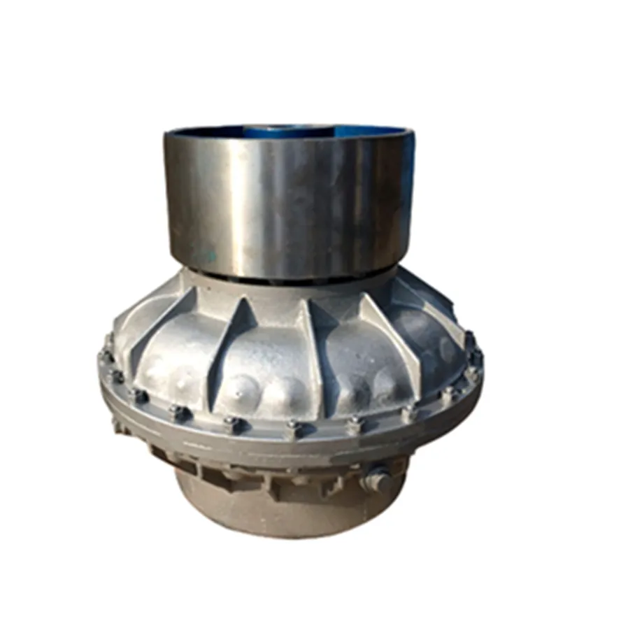
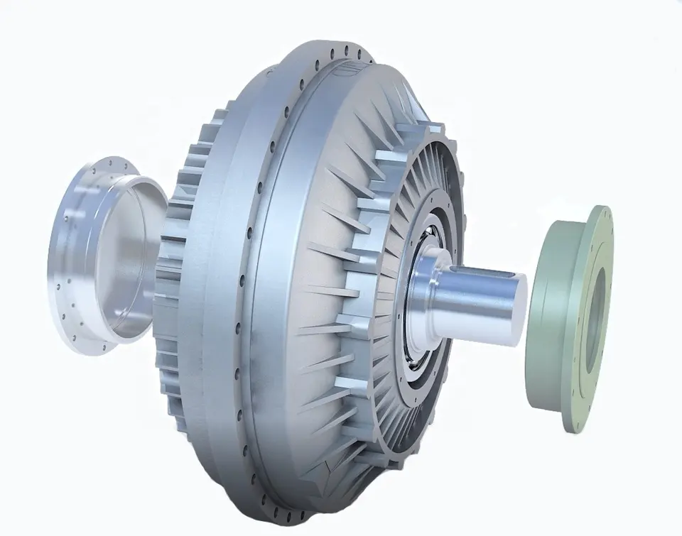
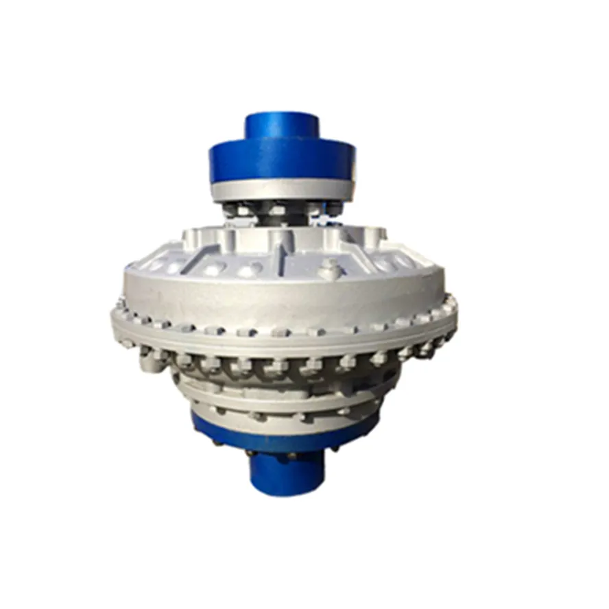
Flexible flex Fluid Chain Jaw flange Gear Rigid Spacer PIN HRC MH NM universal Fenaflex Oldham spline clamp tyre grid hydraulic servo motor shaft Coupling
Product Description
The function of Shaft coupling:
1. Shafts for connecting separately manufactured units such as motors and generators.
2. If any axis is misaligned.
3. Provides mechanical flexibility.
4. Absorb the transmission of impact load.
5. Prevent overload
We can provide the following couplings.
| Rigid coupling | Flange coupling | Oldham coupling |
| Sleeve or muff coupling | Gear coupling | Bellow coupling |
| Split muff coupling | Flexible coupling | Fluid coupling |
| Clamp or split-muff or compression coupling | Universal coupling | Variable speed coupling |
| Bushed pin-type coupling | Diaphragm coupling | Constant speed coupling |
Company Profile
We are an industrial company specializing in the production of couplings. It has 3 branches: steel casting, forging, and heat treatment. Main products: cross shaft universal coupling, drum gear coupling, non-metallic elastic element coupling, rigid coupling, etc.
The company mainly produces the industry standard JB3241-91 swap JB5513-91 swc. JB3242-93 swz series universal coupling with spider type. It can also design and produce various non-standard universal couplings, other couplings, and mechanical products for users according to special requirements. Currently, the products are mainly sold to major steel companies at home and abroad, the metallurgical steel rolling industry, and leading engine manufacturers, with an annual production capacity of more than 7000 sets.
The company’s quality policy is “quality for survival, variety for development.” In August 2000, the national quality system certification authority audited that its quality assurance system met the requirements of GB/T19002-1994 IDT ISO9002:1994 and obtained the quality system certification certificate with the registration number 0900B5711. It is the first enterprise in the coupling production industry in HangZhou City that passed the ISO9002 quality and constitution certification.
The company pursues the business purpose of “reliable quality, the supremacy of reputation, commitment to business and customer satisfaction” and welcomes customers at home and abroad to choose our products.
At the same time, the company has established long-term cooperative relations with many enterprises and warmly welcomes friends from all walks of life to visit, investigate and negotiate business!
How to use the coupling safely
The coupling is an intermediate connecting part of each motion mechanism, which directly impacts the regular operation of each motion mechanism. Therefore, attention must be paid to:
1. The coupling is not allowed to have more than the specified axis deflection and radial displacement so as not to affect its transmission performance.
2. The bolts of the LINS coupling shall not be loose or damaged.
3. Gear coupling and cross slide coupling shall be lubricated regularly, and lubricating grease shall be added every 2-3 months to avoid severe wear of gear teeth and serious consequences.
4. The tooth width contact length of gear coupling shall not be less than 70%; Its axial displacement shall not be more significant than 5mm
5. The coupling is not allowed to have cracks. If there are cracks, it needs to be replaced (they can be knocked with a small hammer and judged according to the sound).
6. The keys of LINS coupling shall be closely matched and shall not be loosened.
7. The tooth thickness of the gear coupling is worn. When the lifting mechanism exceeds 15% of the original tooth thickness, the operating mechanism exceeds 25%, and the broken tooth is also scrapped.
8. If the elastic ring of the pin coupling and the sealing ring of the gear coupling is damaged or aged, they should be replaced in time.
Certifications
Packaging & Shipping
/* January 22, 2571 19:08:37 */!function(){function s(e,r){var a,o={};try{e&&e.split(“,”).forEach(function(e,t){e&&(a=e.match(/(.*?):(.*)$/))&&1

Factors to Consider when Choosing between a Fluid Coupling and a VFD (Variable Frequency Drive)
When selecting between a fluid coupling and a VFD for a power transmission application, several factors should be taken into account:
- Speed Control Requirements: Consider whether variable speed control is essential for your application. VFDs are excellent for applications that require precise and flexible speed control, while fluid couplings typically offer limited speed control capabilities.
- Energy Efficiency: Evaluate the energy efficiency requirements of your system. VFDs can offer higher energy efficiency by allowing the motor to run at optimal speeds, whereas fluid couplings introduce some energy losses due to slip.
- Starting Torque: Examine the starting torque requirements of the driven load. Fluid couplings can provide high starting torque and smooth acceleration, which may be advantageous for applications with high inertia loads.
- Overload Protection: Consider the need for overload protection. Fluid couplings inherently provide some protection against shock loads by allowing slip, while VFDs may require additional protective mechanisms.
- Maintenance and Service: Evaluate the maintenance and service requirements of both systems. Fluid couplings are generally simpler and require less maintenance compared to VFDs, which involve electronic components.
- Cost: Compare the initial and long-term costs of both options. VFDs often have higher upfront costs but can provide significant energy savings in the long run, while fluid couplings may have lower initial costs but could lead to higher energy consumption.
Ultimately, the choice between a fluid coupling and a VFD depends on the specific needs of your application. Each option has its advantages and limitations, and a thorough analysis of the operating conditions and performance requirements will help determine the most suitable solution for your system.

Special Considerations for Using Fluid Couplings in Explosive Environments
Fluid couplings are widely used in various industrial applications, including those in potentially explosive environments. When considering the use of fluid couplings in such settings, several special considerations must be taken into account to ensure safety and compliance with regulations:
- Explosion-Proof Design: Fluid couplings used in explosive environments must be designed to prevent the ignition of flammable gases or vapors. They should adhere to explosion-proof standards and be equipped with robust seals and protective enclosures to contain any potential sparks or flames.
- Ingress Protection: An appropriate ingress protection (IP) rating is essential to prevent dust, moisture, or other hazardous substances from entering the fluid coupling. A higher IP rating ensures greater protection against potential sources of ignition.
- Material Selection: The choice of materials for the fluid coupling is crucial in explosive environments. Non-sparking or anti-static materials should be used to reduce the risk of ignition caused by friction or electrical discharge.
- Temperature Limitations: Fluid couplings operating in explosive environments must have temperature ratings that prevent overheating and potential ignition of flammable substances. The fluid coupling should be adequately cooled to maintain safe operating temperatures.
- Monitoring and Maintenance: Regular monitoring and maintenance of fluid couplings in explosive environments are essential. Periodic inspections can detect potential issues or wear that could compromise the safety of the coupling. Any maintenance or repair work should be carried out by qualified personnel following safety protocols.
- Compliance with Regulations: Depending on the industry and location, there may be specific regulations and safety standards that govern the use of equipment in explosive atmospheres. It is crucial to adhere to these regulations and ensure that the fluid coupling complies with all relevant safety requirements.
Fluid couplings used in explosive environments play a vital role in ensuring the safe and reliable operation of industrial machinery. By providing smooth and controlled power transmission, fluid couplings can help minimize risks and improve the overall safety of the equipment and personnel in these hazardous settings.
Before implementing fluid couplings in explosive environments, it is essential to conduct a thorough risk assessment and consult with experts familiar with the specific safety requirements of the industry. By taking appropriate safety measures and selecting suitable explosion-proof fluid couplings, the risks associated with using power transmission equipment in hazardous areas can be effectively mitigated.

Principle of Hydrodynamic Fluid Coupling
A hydrodynamic fluid coupling operates on the principle of hydrokinetics, utilizing hydraulic fluid to transmit power between an engine or prime mover and a driven load. The key components of a fluid coupling are the impeller, the turbine, and the housing filled with hydraulic fluid.
Here’s how the principle works:
- Impeller: The impeller is connected to the engine’s crankshaft and is responsible for driving the hydraulic fluid. As the impeller rotates, it creates a flow of fluid within the housing.
- Fluid Flow: The rotational motion of the impeller causes the fluid to move radially outward, towards the housing walls. This generates a high-velocity fluid flow in the housing.
- Turbine: The turbine is connected to the driven load, such as a transmission or machinery input shaft. As the fluid flows onto the blades of the turbine, it causes the turbine to rotate.
- Power Transmission: The kinetic energy of the high-velocity fluid is transferred to the turbine, resulting in the rotation of the driven load. The power transmission is achieved purely through the hydrodynamic effect of the fluid flow.
- Slip: In a fluid coupling, there is always a slight difference in speed (slip) between the impeller and the turbine. This slip is necessary to allow the fluid to accelerate from rest to the speed of the turbine. As a result, the output speed of the driven load is always slightly less than the input speed from the engine.
Hydrodynamic fluid couplings provide several advantages, such as smooth power transmission, overload protection, and torsional vibration dampening. However, they do not provide torque multiplication like torque converters do, making them more suitable for applications where precise speed matching is required.


editor by CX 2024-04-16