Product Description
Flexible flex Fluid Chain Jaw flange Gear Rigid Spacer PIN HRC MH NM universal Fenaflex Oldham spline clamp tyre grid hydraulic servo motor shaft Coupling
Product Description
The function of Shaft coupling:
1. Shafts for connecting separately manufactured units such as motors and generators.
2. If any axis is misaligned.
3. Provides mechanical flexibility.
4. Absorb the transmission of impact load.
5. Prevent overload
We can provide the following couplings.
| Rigid coupling | Flange coupling | Oldham coupling |
| Sleeve or muff coupling | Gear coupling | Bellow coupling |
| Split muff coupling | Flexible coupling | Fluid coupling |
| Clamp or split-muff or compression coupling | Universal coupling | Variable speed coupling |
| Bushed pin-type coupling | Diaphragm coupling | Constant speed coupling |
Company Profile
We are an industrial company specializing in the production of couplings. It has 3 branches: steel casting, forging, and heat treatment. Main products: cross shaft universal coupling, drum gear coupling, non-metallic elastic element coupling, rigid coupling, etc.
The company mainly produces the industry standard JB3241-91 swap JB5513-91 swc. JB3242-93 swz series universal coupling with spider type. It can also design and produce various non-standard universal couplings, other couplings, and mechanical products for users according to special requirements. Currently, the products are mainly sold to major steel companies at home and abroad, the metallurgical steel rolling industry, and leading engine manufacturers, with an annual production capacity of more than 7000 sets.
The company’s quality policy is “quality for survival, variety for development.” In August 2000, the national quality system certification authority audited that its quality assurance system met the requirements of GB/T19002-1994 IDT ISO9002:1994 and obtained the quality system certification certificate with the registration number 0900B5711. It is the first enterprise in the coupling production industry in HangZhou City that passed the ISO9002 quality and constitution certification.
The company pursues the business purpose of “reliable quality, the supremacy of reputation, commitment to business and customer satisfaction” and welcomes customers at home and abroad to choose our products.
At the same time, the company has established long-term cooperative relations with many enterprises and warmly welcomes friends from all walks of life to visit, investigate and negotiate business!
How to use the coupling safely
The coupling is an intermediate connecting part of each motion mechanism, which directly impacts the regular operation of each motion mechanism. Therefore, attention must be paid to:
1. The coupling is not allowed to have more than the specified axis deflection and radial displacement so as not to affect its transmission performance.
2. The bolts of the LINS coupling shall not be loose or damaged.
3. Gear coupling and cross slide coupling shall be lubricated regularly, and lubricating grease shall be added every 2-3 months to avoid severe wear of gear teeth and serious consequences.
4. The tooth width contact length of gear coupling shall not be less than 70%; Its axial displacement shall not be more significant than 5mm
5. The coupling is not allowed to have cracks. If there are cracks, it needs to be replaced (they can be knocked with a small hammer and judged according to the sound).
6. The keys of LINS coupling shall be closely matched and shall not be loosened.
7. The tooth thickness of the gear coupling is worn. When the lifting mechanism exceeds 15% of the original tooth thickness, the operating mechanism exceeds 25%, and the broken tooth is also scrapped.
8. If the elastic ring of the pin coupling and the sealing ring of the gear coupling is damaged or aged, they should be replaced in time.
Certifications
Packaging & Shipping
/* January 22, 2571 19:08:37 */!function(){function s(e,r){var a,o={};try{e&&e.split(“,”).forEach(function(e,t){e&&(a=e.match(/(.*?):(.*)$/))&&1
Fluid Coupling and Smooth Power Transmission during Starting and Stopping
A fluid coupling is designed to facilitate smooth power transmission during the starting and stopping phases of machinery and equipment. It achieves this by utilizing the principle of hydrodynamic torque transmission through a fluid medium.
Starting Phase: When power is initially supplied to the input shaft of the fluid coupling, the impeller (also known as the pump) begins to rotate, imparting energy to the fluid inside the coupling. As the fluid gains kinetic energy, it starts moving outward towards the turbine (also called the driven element) due to centrifugal force.
The kinetic energy of the moving fluid causes the turbine to start rotating, transmitting torque to the output shaft. During this starting phase, there is a slight time lag, known as the “slip,” between the impeller and the turbine. However, as the fluid coupling reaches its operational speed, the slip reduces, and the turbine matches the speed of the impeller, resulting in smooth power transmission from the input to the output shaft.
The fluid coupling’s ability to control the slip ensures a gradual and controlled acceleration of the driven equipment, minimizing stress on the drivetrain components and preventing sudden shock loads.
Stopping Phase: When power to the input shaft is reduced or cut off, the impeller slows down, and the kinetic energy in the fluid decreases. As a result, the fluid moves away from the turbine towards the center of the coupling, reducing the torque transmission between the input and output shafts.
This characteristic of the fluid coupling aids in smoothly decelerating the connected equipment, preventing sudden jolts or jerks during the stopping process. The ability to control the slip during deceleration ensures that the driven machinery comes to a gradual and controlled stop, enhancing safety and protecting the equipment from damage.
The combination of hydrodynamic torque transmission and the ability to control the slip makes fluid couplings ideal for applications where smooth power transmission during starting and stopping is essential. Industries such as mining, construction, metal processing, marine propulsion, and power generation benefit from the reliable and efficient performance of fluid couplings in various machinery and equipment.

Fluid Coupling’s Handling of Load Changes during Operation
Fluid couplings are designed to efficiently handle changes in load conditions during operation, providing smooth and controlled power transmission. Here’s how fluid couplings accomplish this:
1. Torque Sensing: Fluid couplings are torque-sensitive devices. As the load on the driving side varies, the torque transmitted through the fluid coupling adjusts accordingly. When the load increases, the fluid coupling allows for some slip between the input and output sides, absorbing the excess torque. Conversely, when the load decreases, the fluid coupling reduces slip and transmits more torque, accommodating the new load conditions.
2. Load Distribution: In multi-drive systems, fluid couplings help to distribute the load evenly among connected equipment. When one machine experiences a higher load, the fluid coupling redistributes torque to prevent overloading of a specific component, ensuring a balanced power distribution.
3. Smooth Power Transmission: Fluid couplings offer a smooth and gradual transmission of power, even during load changes. Unlike mechanical clutches or direct couplings, fluid couplings provide a dampening effect, reducing shock loads and torsional vibrations when the load fluctuates. This minimizes stress on the connected machinery and enhances overall system reliability.
4. Soft Start and Stop: One of the significant advantages of fluid couplings is their ability to facilitate soft start and stop operations. During startup, the fluid coupling allows for controlled slip, gradually increasing the speed of the driven equipment. Similarly, during shutdown, the fluid coupling smoothly decelerates the connected machinery, preventing sudden stops that could cause damage or excessive wear.
5. Overload Protection: In situations where the load surpasses the rated capacity, the fluid coupling acts as an overload protector. By slipping and absorbing excess torque, it prevents damage to the connected equipment and the fluid coupling itself. This overload protection contributes to the safety and longevity of the entire system.
6. Automatic Adjustment: Fluid couplings automatically adjust to variations in load conditions without the need for manual intervention. This feature makes them suitable for applications with changing load demands, such as conveyors, crushers, pumps, and fans.
Overall, the ability of fluid couplings to handle changes in load conditions ensures stable and efficient power transmission while protecting the machinery from abrupt stress and wear. This makes fluid couplings an excellent choice for various industrial applications that require reliable and flexible power transfer.
Environmental Concerns Related to Fluid Coupling Operation
Fluid couplings are generally considered environmentally friendly and pose minimal direct environmental concerns during their operation. They do not contain hazardous materials or produce harmful emissions, making them a relatively safe choice for power transmission systems.
However, it is essential to consider some potential indirect environmental impacts associated with the use of fluid couplings in certain applications:
- Energy Efficiency: As discussed earlier, fluid couplings can improve energy efficiency in power transmission systems. By reducing energy wastage and optimizing torque transmission, they indirectly contribute to lower energy consumption. Energy efficiency is crucial in industries where high power consumption may have environmental implications due to increased energy demand from power plants.
- Maintenance Practices: Regular maintenance is essential to ensure optimal performance and longevity of fluid couplings. Proper maintenance reduces the risk of leaks and other potential issues that could lead to fluid spillage. Implementing sound maintenance practices can prevent environmental contamination and contribute to sustainable operations.
- Fluid Selection: The choice of fluid used in the coupling can impact the environment. While most fluid couplings use environmentally safe hydraulic fluids, it is essential to ensure that the selected fluid complies with environmental regulations and does not pose any environmental hazards if accidentally released.
- End-of-Life Disposal: At the end of their lifecycle, fluid couplings may need to be disposed of properly. The recycling or disposal of fluid couplings should follow local environmental regulations to minimize any potential environmental impact.
Overall, fluid couplings themselves are not a significant source of environmental concerns. Still, it is essential to consider their indirect impacts, such as energy efficiency, maintenance practices, fluid selection, and end-of-life disposal, to ensure responsible and environmentally conscious use.


editor by CX 2024-05-13
China Custom Flange Cast Iron Coupling Steel Universal Joint Cardan Pump Rubber Motor Disc Curved Tooth Flex Rigid Drive Shaft Nm Yox Fluid Jaw Flexible Chain Gear Couplings
Product Description
Excellent powder metallurgy parts metallic sintered parts
We could offer various powder metallurgy parts including iron based and copper based with top quality and cheapest price, please only send the drawing or sample to us, we will according to customer’s requirement to make it. if you are interested in our product, please do not hesitate to contact us, we would like to offer the top quality and best service for you. thank you!
How do We Work with Our Clients
1. For a design expert or a big company with your own engineering team: we prefer to receive a fully RFQ pack from you including drawing, 3D model, quantity, pictures;
2. For a start-up company owner or green hand for engineering: just send an idea that you want to try, you don’t even need to know what casting is;
3. Our sales will reply you within 24 hours to confirm further details and give the estimated quote time;
4. Our engineering team will evaluate your inquiry and provide our offer within next 1~3 working days.
5. We can arrange a technical communication meeting with you and our engineers together anytime if required.
| Place of origin: | Jangsu,China |
| Type: | Powder metallurgy sintering |
| Spare parts type: | Powder metallurgy parts |
| Machinery Test report: | Provided |
| Material: | Iron,stainless,steel,copper |
| Key selling points: | Quality assurance |
| Mould type: | Tungsten steel |
| Material standard: | MPIF 35,DIN 3571,JIS Z 2550 |
| Application: | Small home appliances,Lockset,Electric tool, automobile, |
| Brand Name: | OEM SERVICE |
| Plating: | Customized |
| After-sales Service: | Online support |
| Processing: | Powder Metallurgr,CNC Machining |
| Powder Metallurgr: | High frequency quenching, oil immersion |
| Quality Control: | 100% inspection |
The Advantage of Powder Metallurgy Process
1. Cost effective
The final products can be compacted with powder metallurgy method ,and no need or can shorten the processing of machine .It can save material greatly and reduce the production cost .
2. Complex shapes
Powder metallurgy allows to obtain complex shapes directly from the compacting tooling ,without any machining operation ,like teeth ,splines ,profiles ,frontal geometries etc.
3. High precision
Achievable tolerances in the perpendicular direction of compacting are typically IT 8-9 as sintered,improvable up to IT 5-7 after sizing .Additional machining operations can improve the precision .
4. Self-lubrication
The interconnected porosity of the material can be filled with oils ,obtaining then a self-lubricating bearing :the oil provides constant lubrication between bearing and shaft ,and the system does not need any additional external lubricant .
5. Green technology
The manufacturing process of sintered components is certified as ecological ,because the material waste is very low ,the product is recyclable ,and the energy efficiency is good because the material is not molten.
FAQ
Q1: What is the type of payment?
A: Usually you should prepay 50% of the total amount. The balance should be pay off before shipment.
Q2: How to guarantee the high quality?
A: 100% inspection. We have Carl Zeiss high-precision testing equipment and testing department to make sure every product of size,appearance and pressure test are good.
Q3: How long will you give me the reply?
A: we will contact you in 12 hours as soon as we can.
Q4. How about your delivery time?
A: Generally, it will take 25 to 35 days after receiving your advance payment. The specific delivery time depends on the items and the quantity of your order. and if the item was non standard, we have to consider extra 10-15days for tooling/mould made.
Q5. Can you produce according to the samples or drawings?
A: Yes, we can produce by your samples or technical drawings. We can build the molds and fixtures.
Q6: How about tooling Charge?
A: Tooling charge only charge once when first order, all future orders would not charge again even tooling repair or under maintance.
Q7: What is your sample policy?
A: We can supply the sample if we have ready parts in stock, but the customers have to pay the sample cost and the courier cost.
Q8: How do you make our business long-term and good relationship?
A: 1. We keep good quality and competitive price to ensure our customers benefit ;
2. We respect every customer as our friend and we sincerely do business and make friends with them, no matter where they come from.
/* January 22, 2571 19:08:37 */!function(){function s(e,r){var a,o={};try{e&&e.split(“,”).forEach(function(e,t){e&&(a=e.match(/(.*?):(.*)$/))&&1
Impact of Fluid Coupling on the Overall Reliability of a Power Transmission System
A fluid coupling can significantly contribute to the overall reliability of a power transmission system in various ways:
- Smooth Power Transmission: Fluid couplings facilitate smooth power transmission between the driving and driven components, minimizing shocks and vibrations during startup and operation. This reduces the risk of sudden failures or damages to connected equipment.
- Overload Protection: Fluid couplings offer inherent overload protection by allowing controlled slip during sudden load changes or overloads. This protects the system from excessive stresses and prevents damage to the motor and driven machinery.
- Reduced Mechanical Wear: The smooth operation of fluid couplings reduces mechanical wear on connected components, such as gearboxes, belts, and chains. This results in longer service life and decreased maintenance requirements.
- Increased Equipment Life: By reducing stress and wear on the entire power transmission system, fluid couplings can extend the service life of motors, gearboxes, and other components. This enhances the overall reliability of the system over an extended period.
- Enhanced System Safety: The ability of fluid couplings to protect against shock loads and overloads enhances the safety of personnel working with or near the machinery. It prevents sudden and unpredictable movements, reducing the risk of accidents and injuries.
- Stable Performance: Fluid couplings maintain a constant speed ratio between the driving and driven shafts, ensuring stable and predictable performance of the power transmission system. This predictability aids in maintaining process stability and efficiency.
Incorporating a properly sized and selected fluid coupling into a power transmission system can improve its reliability, reduce downtime, and prevent costly breakdowns. Regular maintenance and monitoring of the fluid coupling also play a crucial role in ensuring long-term reliability and trouble-free operation.

Contribution of Fluid Coupling to the Overall Efficiency of a Mechanical System
A fluid coupling plays a crucial role in improving the overall efficiency of a mechanical system, especially in applications where smooth power transmission, soft-starting, and torque control are essential. Here’s how a fluid coupling contributes to system efficiency:
1. Smooth Power Transmission:
Fluid couplings provide a smooth and gradual transfer of power from the driving to the driven machinery. The absence of direct mechanical contact between the input and output shafts reduces shock loads and vibrations, leading to less wear and tear on the connected equipment. This smooth power transmission results in increased system efficiency and reduced downtime.
2. Soft-Start Capability:
Fluid couplings offer soft-starting functionality, which is particularly beneficial for high-inertia or heavy-load applications. During startup, the fluid coupling allows the input shaft to gradually accelerate the output shaft, preventing sudden jerks or torque spikes. Soft-starting not only protects the mechanical components but also reduces energy consumption during the starting phase, contributing to overall efficiency.
3. Torque Control:
Fluid couplings enable precise control over the torque transmitted between the driving and driven machinery. By adjusting the fill level or using variable speed couplings, the torque output can be fine-tuned to match the requirements of the application. This feature ensures optimal performance and energy efficiency, especially in systems where torque demand varies during operation.
4. Overload Protection:
In case of sudden overloads or jamming of the driven machinery, the fluid coupling acts as a torque limiter. It will slip and absorb excess torque, protecting the mechanical system from damage. This overload protection not only safeguards the equipment but also contributes to the longevity and efficiency of the entire system.
5. Heat Dissipation:
Fluid couplings can absorb and dissipate heat generated during continuous operations. This heat dissipation capability prevents the system from overheating, ensuring consistent performance and avoiding thermal damage to the machinery. By maintaining proper operating temperatures, the fluid coupling aids in improving overall efficiency.
6. Energy Savings:
With its ability to reduce shock loads and provide smooth acceleration, a fluid coupling can help save energy during starting and stopping cycles. The elimination of mechanical shocks and vibrations reduces energy losses, resulting in higher overall energy efficiency.
In summary, a fluid coupling enhances the overall efficiency of a mechanical system by providing smooth power transmission, soft-start capability, precise torque control, overload protection, heat dissipation, and energy savings. Its contributions to reduced wear and tear, energy-efficient operations, and enhanced equipment lifespan make it a valuable component in various industrial applications.

Can Fluid Couplings be Retrofitted into Existing Machinery?
Yes, fluid couplings can be retrofitted into existing machinery in many cases. Retrofitting is a process of adding new components or technologies to existing equipment to improve its performance or functionality. Fluid couplings are versatile and can often be integrated into various industrial machines and power transmission systems.
The process of retrofitting a fluid coupling involves several steps:
- Evaluation: Before retrofitting, a thorough evaluation of the existing machinery is necessary. Engineers need to assess the machine’s design, power requirements, and other relevant factors to determine the suitability of a fluid coupling.
- Compatibility: Fluid couplings should be compatible with the existing machine’s shaft, motor, and driven equipment. If necessary, modifications may be required to ensure a proper fit.
- Installation: The installation process involves mounting the fluid coupling onto the machine’s shaft and connecting it to the motor and driven equipment.
- Alignment: Precise alignment of the fluid coupling is crucial for optimal performance and to avoid issues such as vibration and wear.
- Testing: After installation, the retrofitted system undergoes testing to ensure that it functions as intended and meets the desired performance goals.
Retrofitting fluid couplings can offer various benefits, including:
- Improved Energy Efficiency: Fluid couplings can enhance energy efficiency by reducing power losses and improving the overall power transmission system’s efficiency.
- Enhanced Protection: Fluid couplings provide protection against shocks and overloads, safeguarding the machinery and its components from damage.
- Reduced Maintenance: The smooth start and reduced stress on the machine during operation can lead to lower maintenance requirements and longer equipment lifespan.
- Soft Start: Fluid couplings offer a soft start, which reduces the mechanical stress on the machine during startup, extending its life and minimizing downtime.
However, it is essential to involve qualified engineers and technicians for the retrofitting process to ensure proper installation, alignment, and performance of the fluid coupling in the existing machinery.
editor by CX 2024-05-02
China factory Flange Cast Iron Coupling Steel Universal Joint Cardan Pump Rubber Motor Disc Curved Tooth Flex Rigid Drive Shaft Nm Yox Fluid Jaw Flexible Chain Gear Couplings
Product Description
Excellent powder metallurgy parts metallic sintered parts
We could offer various powder metallurgy parts including iron based and copper based with top quality and cheapest price, please only send the drawing or sample to us, we will according to customer’s requirement to make it. if you are interested in our product, please do not hesitate to contact us, we would like to offer the top quality and best service for you. thank you!
How do We Work with Our Clients
1. For a design expert or a big company with your own engineering team: we prefer to receive a fully RFQ pack from you including drawing, 3D model, quantity, pictures;
2. For a start-up company owner or green hand for engineering: just send an idea that you want to try, you don’t even need to know what casting is;
3. Our sales will reply you within 24 hours to confirm further details and give the estimated quote time;
4. Our engineering team will evaluate your inquiry and provide our offer within next 1~3 working days.
5. We can arrange a technical communication meeting with you and our engineers together anytime if required.
| Place of origin: | Jangsu,China |
| Type: | Powder metallurgy sintering |
| Spare parts type: | Powder metallurgy parts |
| Machinery Test report: | Provided |
| Material: | Iron,stainless,steel,copper |
| Key selling points: | Quality assurance |
| Mould type: | Tungsten steel |
| Material standard: | MPIF 35,DIN 3571,JIS Z 2550 |
| Application: | Small home appliances,Lockset,Electric tool, automobile, |
| Brand Name: | OEM SERVICE |
| Plating: | Customized |
| After-sales Service: | Online support |
| Processing: | Powder Metallurgr,CNC Machining |
| Powder Metallurgr: | High frequency quenching, oil immersion |
| Quality Control: | 100% inspection |
The Advantage of Powder Metallurgy Process
1. Cost effective
The final products can be compacted with powder metallurgy method ,and no need or can shorten the processing of machine .It can save material greatly and reduce the production cost .
2. Complex shapes
Powder metallurgy allows to obtain complex shapes directly from the compacting tooling ,without any machining operation ,like teeth ,splines ,profiles ,frontal geometries etc.
3. High precision
Achievable tolerances in the perpendicular direction of compacting are typically IT 8-9 as sintered,improvable up to IT 5-7 after sizing .Additional machining operations can improve the precision .
4. Self-lubrication
The interconnected porosity of the material can be filled with oils ,obtaining then a self-lubricating bearing :the oil provides constant lubrication between bearing and shaft ,and the system does not need any additional external lubricant .
5. Green technology
The manufacturing process of sintered components is certified as ecological ,because the material waste is very low ,the product is recyclable ,and the energy efficiency is good because the material is not molten.
FAQ
Q1: What is the type of payment?
A: Usually you should prepay 50% of the total amount. The balance should be pay off before shipment.
Q2: How to guarantee the high quality?
A: 100% inspection. We have Carl Zeiss high-precision testing equipment and testing department to make sure every product of size,appearance and pressure test are good.
Q3: How long will you give me the reply?
A: we will contact you in 12 hours as soon as we can.
Q4. How about your delivery time?
A: Generally, it will take 25 to 35 days after receiving your advance payment. The specific delivery time depends on the items and the quantity of your order. and if the item was non standard, we have to consider extra 10-15days for tooling/mould made.
Q5. Can you produce according to the samples or drawings?
A: Yes, we can produce by your samples or technical drawings. We can build the molds and fixtures.
Q6: How about tooling Charge?
A: Tooling charge only charge once when first order, all future orders would not charge again even tooling repair or under maintance.
Q7: What is your sample policy?
A: We can supply the sample if we have ready parts in stock, but the customers have to pay the sample cost and the courier cost.
Q8: How do you make our business long-term and good relationship?
A: 1. We keep good quality and competitive price to ensure our customers benefit ;
2. We respect every customer as our friend and we sincerely do business and make friends with them, no matter where they come from.
/* January 22, 2571 19:08:37 */!function(){function s(e,r){var a,o={};try{e&&e.split(“,”).forEach(function(e,t){e&&(a=e.match(/(.*?):(.*)$/))&&1
What are the Differences between Fluid Couplings and Mechanical Clutches?
Fluid couplings and mechanical clutches are both components used in power transmission systems, but they operate on different principles and have distinct characteristics:
- Operating Principle:
- Fluid Coupling: A fluid coupling uses hydraulic fluid to transmit torque. It consists of an impeller and a runner immersed in a fluid-filled chamber. When the input shaft (driving member) rotates, it imparts motion to the fluid, which in turn drives the output shaft (driven member).
- Mechanical Clutch: A mechanical clutch relies on physical contact between friction surfaces to transmit torque. When engaged, the clutch plates or discs press against each other, creating a mechanical link between the input and output shafts.
- Slippage:
- Fluid Coupling: Fluid couplings allow a certain degree of slippage between the input and output shafts. This slippage provides a smooth start and helps protect the machinery from shock loads.
- Mechanical Clutch: Mechanical clutches have minimal slippage when engaged, providing a direct and rigid connection between the input and output shafts.
- Control:
- Fluid Coupling: Fluid couplings provide automatic torque transmission without the need for manual engagement or disengagement.
- Mechanical Clutch: Mechanical clutches require manual actuation to engage or disengage, allowing for precise control over power transmission.
- Heat Dissipation:
- Fluid Coupling: Fluid couplings dissipate heat generated during operation, which helps prevent overheating of the system.
- Mechanical Clutch: Mechanical clutches may generate more heat due to friction, requiring additional cooling mechanisms in high-power applications.
- Applications:
- Fluid Coupling: Fluid couplings are commonly used in heavy machinery, such as mining equipment, crushers, and conveyors, where shock absorption and smooth starts are crucial.
- Mechanical Clutch: Mechanical clutches are prevalent in applications where precise engagement and disengagement are required, such as automotive transmissions and manual industrial machinery.
While both fluid couplings and mechanical clutches serve the purpose of transmitting torque, their different operating principles and features make them suitable for specific applications and operating conditions.
Contribution of Fluid Coupling to the Overall Efficiency of a Mechanical System
A fluid coupling plays a crucial role in improving the overall efficiency of a mechanical system, especially in applications where smooth power transmission, soft-starting, and torque control are essential. Here’s how a fluid coupling contributes to system efficiency:
1. Smooth Power Transmission:
Fluid couplings provide a smooth and gradual transfer of power from the driving to the driven machinery. The absence of direct mechanical contact between the input and output shafts reduces shock loads and vibrations, leading to less wear and tear on the connected equipment. This smooth power transmission results in increased system efficiency and reduced downtime.
2. Soft-Start Capability:
Fluid couplings offer soft-starting functionality, which is particularly beneficial for high-inertia or heavy-load applications. During startup, the fluid coupling allows the input shaft to gradually accelerate the output shaft, preventing sudden jerks or torque spikes. Soft-starting not only protects the mechanical components but also reduces energy consumption during the starting phase, contributing to overall efficiency.
3. Torque Control:
Fluid couplings enable precise control over the torque transmitted between the driving and driven machinery. By adjusting the fill level or using variable speed couplings, the torque output can be fine-tuned to match the requirements of the application. This feature ensures optimal performance and energy efficiency, especially in systems where torque demand varies during operation.
4. Overload Protection:
In case of sudden overloads or jamming of the driven machinery, the fluid coupling acts as a torque limiter. It will slip and absorb excess torque, protecting the mechanical system from damage. This overload protection not only safeguards the equipment but also contributes to the longevity and efficiency of the entire system.
5. Heat Dissipation:
Fluid couplings can absorb and dissipate heat generated during continuous operations. This heat dissipation capability prevents the system from overheating, ensuring consistent performance and avoiding thermal damage to the machinery. By maintaining proper operating temperatures, the fluid coupling aids in improving overall efficiency.
6. Energy Savings:
With its ability to reduce shock loads and provide smooth acceleration, a fluid coupling can help save energy during starting and stopping cycles. The elimination of mechanical shocks and vibrations reduces energy losses, resulting in higher overall energy efficiency.
In summary, a fluid coupling enhances the overall efficiency of a mechanical system by providing smooth power transmission, soft-start capability, precise torque control, overload protection, heat dissipation, and energy savings. Its contributions to reduced wear and tear, energy-efficient operations, and enhanced equipment lifespan make it a valuable component in various industrial applications.

Controlling Torque and Rotational Speed with Fluid Couplings
A fluid coupling plays a crucial role in controlling torque and rotational speed in power transmission systems. The principle behind its operation allows for smooth torque transmission while offering some level of speed control:
- Torque Transmission: When power is applied to the input side (also known as the driving side) of the fluid coupling, the impeller starts to rotate and accelerates the transmission fluid inside the housing. The kinetic energy of the moving fluid creates a rotating flow pattern that transfers torque to the output side (also known as the driven side) of the coupling. This torque transfer enables the connected machinery or equipment to start smoothly without any shock loading.
- Slip: In a fluid coupling, there is always a slight difference in speed between the input and output sides due to the viscous nature of the fluid. This speed difference is known as slip. The slip allows the fluid coupling to protect the connected components from sudden torque spikes and vibrations. If the output side experiences an abrupt load increase or jam, the slip absorbs the excess torque, preventing damage to the drivetrain.
- Speed Control: While fluid couplings are not as efficient in speed control as variable-speed drives, they do offer some inherent speed control characteristics. The amount of slip in the fluid coupling affects the output speed relative to the input speed. By adjusting the fill level of the fluid coupling or using different fluid viscosities, it is possible to fine-tune the speed at which the output shaft rotates. However, it’s important to note that this speed control is limited compared to other speed control mechanisms.
Overall, fluid couplings provide a reliable and efficient means of controlling torque during power transmission. Their ability to dampen torsional vibrations and provide overload protection makes them suitable for various applications where smooth torque transfer and protection against shock loads are essential.
editor by CX 2024-04-25
China Good quality Flange Cast Iron Coupling Steel Universal Joint Cardan Pump Rubber Motor Disc Curved Tooth Flex Rigid Drive Shaft Nm Yox Fluid Jaw Flexible Chain Gear Couplings
Product Description
Excellent powder metallurgy parts metallic sintered parts
We could offer various powder metallurgy parts including iron based and copper based with top quality and cheapest price, please only send the drawing or sample to us, we will according to customer’s requirement to make it. if you are interested in our product, please do not hesitate to contact us, we would like to offer the top quality and best service for you. thank you!
How do We Work with Our Clients
1. For a design expert or a big company with your own engineering team: we prefer to receive a fully RFQ pack from you including drawing, 3D model, quantity, pictures;
2. For a start-up company owner or green hand for engineering: just send an idea that you want to try, you don’t even need to know what casting is;
3. Our sales will reply you within 24 hours to confirm further details and give the estimated quote time;
4. Our engineering team will evaluate your inquiry and provide our offer within next 1~3 working days.
5. We can arrange a technical communication meeting with you and our engineers together anytime if required.
| Place of origin: | Jangsu,China |
| Type: | Powder metallurgy sintering |
| Spare parts type: | Powder metallurgy parts |
| Machinery Test report: | Provided |
| Material: | Iron,stainless,steel,copper |
| Key selling points: | Quality assurance |
| Mould type: | Tungsten steel |
| Material standard: | MPIF 35,DIN 3571,JIS Z 2550 |
| Application: | Small home appliances,Lockset,Electric tool, automobile, |
| Brand Name: | OEM SERVICE |
| Plating: | Customized |
| After-sales Service: | Online support |
| Processing: | Powder Metallurgr,CNC Machining |
| Powder Metallurgr: | High frequency quenching, oil immersion |
| Quality Control: | 100% inspection |
The Advantage of Powder Metallurgy Process
1. Cost effective
The final products can be compacted with powder metallurgy method ,and no need or can shorten the processing of machine .It can save material greatly and reduce the production cost .
2. Complex shapes
Powder metallurgy allows to obtain complex shapes directly from the compacting tooling ,without any machining operation ,like teeth ,splines ,profiles ,frontal geometries etc.
3. High precision
Achievable tolerances in the perpendicular direction of compacting are typically IT 8-9 as sintered,improvable up to IT 5-7 after sizing .Additional machining operations can improve the precision .
4. Self-lubrication
The interconnected porosity of the material can be filled with oils ,obtaining then a self-lubricating bearing :the oil provides constant lubrication between bearing and shaft ,and the system does not need any additional external lubricant .
5. Green technology
The manufacturing process of sintered components is certified as ecological ,because the material waste is very low ,the product is recyclable ,and the energy efficiency is good because the material is not molten.
FAQ
Q1: What is the type of payment?
A: Usually you should prepay 50% of the total amount. The balance should be pay off before shipment.
Q2: How to guarantee the high quality?
A: 100% inspection. We have Carl Zeiss high-precision testing equipment and testing department to make sure every product of size,appearance and pressure test are good.
Q3: How long will you give me the reply?
A: we will contact you in 12 hours as soon as we can.
Q4. How about your delivery time?
A: Generally, it will take 25 to 35 days after receiving your advance payment. The specific delivery time depends on the items and the quantity of your order. and if the item was non standard, we have to consider extra 10-15days for tooling/mould made.
Q5. Can you produce according to the samples or drawings?
A: Yes, we can produce by your samples or technical drawings. We can build the molds and fixtures.
Q6: How about tooling Charge?
A: Tooling charge only charge once when first order, all future orders would not charge again even tooling repair or under maintance.
Q7: What is your sample policy?
A: We can supply the sample if we have ready parts in stock, but the customers have to pay the sample cost and the courier cost.
Q8: How do you make our business long-term and good relationship?
A: 1. We keep good quality and competitive price to ensure our customers benefit ;
2. We respect every customer as our friend and we sincerely do business and make friends with them, no matter where they come from.
/* January 22, 2571 19:08:37 */!function(){function s(e,r){var a,o={};try{e&&e.split(“,”).forEach(function(e,t){e&&(a=e.match(/(.*?):(.*)$/))&&1

Contribution of Fluid Coupling to the Longevity of Connected Equipment
A fluid coupling plays a crucial role in enhancing the longevity and protecting the connected equipment by providing the following benefits:
- Shock Load Damping: When the equipment starts or stops, there can be sudden changes in torque, resulting in shock loads. The fluid coupling absorbs and dampens these shock loads, reducing stress and wear on the connected equipment.
- Torsional Vibration Damping: Torsional vibrations can occur during the operation of the connected equipment, which can be damaging over time. The fluid coupling acts as a torsional damper, reducing these vibrations and preventing potential fatigue failure in the equipment.
- Overload Protection: In case of sudden overloads or jamming of the connected equipment, the fluid coupling can slip and decouple the load, protecting both the equipment and the driving motor from excessive stress and damage.
- Smooth Startup: During startup, the fluid coupling allows a gradual increase in torque, enabling a smooth and controlled acceleration of the connected equipment. This eliminates sudden jerks and reduces mechanical stress during the startup phase.
- Load Distribution: The fluid coupling distributes the load evenly across the connected equipment, minimizing wear and tear on specific components and extending the overall lifespan of the machinery.
- Reduced Maintenance: By reducing shock loads and vibrations, the fluid coupling helps decrease the frequency of maintenance and repairs required for the connected equipment, resulting in cost savings and improved uptime.
- Energy Efficiency: The fluid coupling allows for efficient power transmission by reducing losses during startup and load changes. This, in turn, helps in lowering the overall energy consumption of the system and contributes to equipment longevity.
- Contamination Prevention: The fluid coupling encapsulates the driving and driven components, providing a barrier that helps prevent contaminants such as dust, dirt, and moisture from entering the equipment’s internal components. This protection can extend the life of bearings and other sensitive parts.
Overall, a fluid coupling acts as a protective intermediary between the driving motor and the connected equipment, enhancing the system’s reliability, efficiency, and longevity by mitigating the effects of shocks, vibrations, and overloads.

Fluid Couplings in High-Temperature Environments
Fluid couplings are versatile power transmission devices commonly used in various industrial applications. However, their suitability for high-temperature environments depends on several factors, including the design, materials, and the specific operating conditions.
Here are some key considerations regarding the use of fluid couplings in high-temperature environments:
- Fluid Type: The type of fluid used inside the coupling greatly influences its temperature capabilities. Some fluid couplings are designed to handle higher temperatures by using specially formulated high-temperature fluids that can withstand elevated heat levels without degradation.
- Materials: The materials used in the construction of the fluid coupling play a crucial role in determining its maximum temperature tolerance. High-quality materials with good heat resistance properties are required to ensure reliable performance in high-temperature conditions.
- Lubrication: Proper lubrication is essential to reduce friction and heat generation within the fluid coupling. In high-temperature environments, ensuring sufficient and appropriate lubrication is crucial to prevent excessive wear and potential damage.
- Cooling: Some fluid couplings come equipped with cooling systems, such as cooling fins or external cooling circuits, to dissipate excess heat generated during operation. These cooling mechanisms can enhance the coupling’s capacity to handle higher temperatures.
- Application Considerations: The specific application and load requirements must be taken into account. In some cases, high-temperature conditions may be intermittent or occasional, allowing the fluid coupling to cool down between cycles. However, continuous high-temperature operation may require a more robust and specialized fluid coupling.
It is important to consult with the fluid coupling manufacturer to understand the temperature limitations and performance capabilities of their products. Manufacturers can provide guidance on selecting the appropriate fluid coupling for specific high-temperature applications.
While fluid couplings can be suitable for moderate to high-temperature environments, it is essential to operate them within their specified temperature range to ensure optimal performance and longevity. Extreme temperatures beyond the coupling’s rated limits can lead to accelerated wear, reduced efficiency, and potential damage, ultimately affecting the reliability of the power transmission system.
In summary, fluid couplings can be used in high-temperature environments, provided that the coupling’s design, materials, and lubrication are suitable for the specific application and operating conditions. Regular maintenance and adherence to the manufacturer’s guidelines are essential to ensure reliable performance and durability in such environments.
Examples of Industries Using Fluid Couplings
Fluid couplings find applications in various industries where smooth power transmission and torque control are required. Some common industries that commonly use fluid couplings include:
- Mining: Fluid couplings are used in mining equipment such as conveyors, crushers, and excavators to provide controlled startup and overload protection.
- Construction: Construction machinery like cranes, loaders, and piling rigs use fluid couplings for efficient power transmission and reduced shock loads.
- Marine: Fluid couplings are employed in marine propulsion systems to optimize engine performance and protect against sudden load changes.
- Steel and Metal Processing: Industries dealing with metal processing use fluid couplings in rolling mills, coilers, and metal forming machines for soft start and overload protection.
- Pulp and Paper: Pulp and paper mills utilize fluid couplings in various equipment, such as chippers, conveyors, and pumps, for smooth power transmission.
- Automotive: In automotive applications, fluid couplings can be found in torque converters, which provide smooth torque transmission in automatic transmissions.
- Energy and Power Generation: Fluid couplings are used in power plants for applications like fans, pumps, and turbines to control power transmission and reduce mechanical stress during startup.
- Wastewater Treatment: Fluid couplings are used in wastewater treatment plants for applications like aerators and pumps, ensuring efficient power transmission and equipment protection.
- Food and Beverage: Industries dealing with food processing and beverage production use fluid couplings in various applications to ensure gentle power transmission and prevent sudden load shocks.
- Chemical and Petrochemical: Fluid couplings are used in pumps and mixers in chemical and petrochemical processing to control torque and protect equipment.
These examples illustrate the versatility of fluid couplings and their widespread use across diverse industries to enhance the efficiency and safety of power transmission systems.
editor by CX 2024-04-24
China Standard Flexible Flex Fluid Chain Jaw Flange Gear Rigid Spacer Pin HRC Mh Nm Universal Fenaflex Oldham Spline Clamp Tyre Grid Hydraulic Servo Motor Shaft Coupling
Product Description
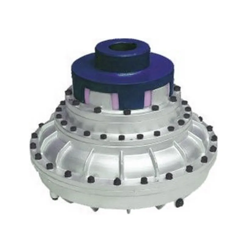
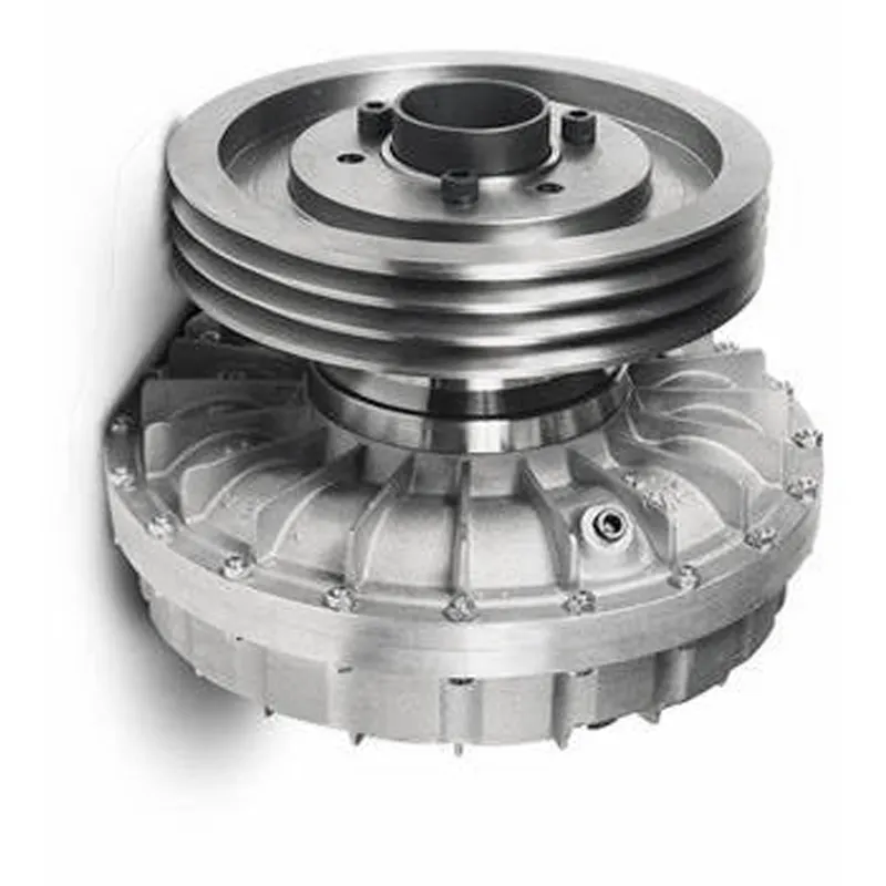
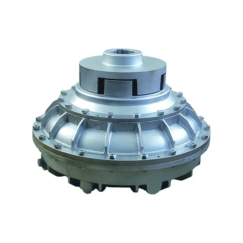
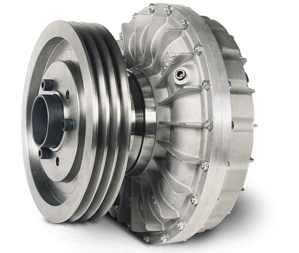
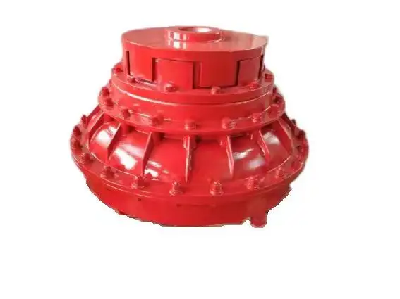
Flexible flex Fluid Chain Jaw flange Gear Rigid Spacer PIN HRC MH NM universal Fenaflex Oldham spline clamp tyre grid hydraulic servo motor shaft Coupling
Product Description
The function of Shaft coupling:
1. Shafts for connecting separately manufactured units such as motors and generators.
2. If any axis is misaligned.
3. Provides mechanical flexibility.
4. Absorb the transmission of impact load.
5. Prevent overload
We can provide the following couplings.
| Rigid coupling | Flange coupling | Oldham coupling |
| Sleeve or muff coupling | Gear coupling | Bellow coupling |
| Split muff coupling | Flexible coupling | Fluid coupling |
| Clamp or split-muff or compression coupling | Universal coupling | Variable speed coupling |
| Bushed pin-type coupling | Diaphragm coupling | Constant speed coupling |
Company Profile
We are an industrial company specializing in the production of couplings. It has 3 branches: steel casting, forging, and heat treatment. Main products: cross shaft universal coupling, drum gear coupling, non-metallic elastic element coupling, rigid coupling, etc.
The company mainly produces the industry standard JB3241-91 swap JB5513-91 swc. JB3242-93 swz series universal coupling with spider type. It can also design and produce various non-standard universal couplings, other couplings, and mechanical products for users according to special requirements. Currently, the products are mainly sold to major steel companies at home and abroad, the metallurgical steel rolling industry, and leading engine manufacturers, with an annual production capacity of more than 7000 sets.
The company’s quality policy is “quality for survival, variety for development.” In August 2000, the national quality system certification authority audited that its quality assurance system met the requirements of GB/T19002-1994 IDT ISO9002:1994 and obtained the quality system certification certificate with the registration number 0900B5711. It is the first enterprise in the coupling production industry in HangZhou City that passed the ISO9002 quality and constitution certification.
The company pursues the business purpose of “reliable quality, the supremacy of reputation, commitment to business and customer satisfaction” and welcomes customers at home and abroad to choose our products.
At the same time, the company has established long-term cooperative relations with many enterprises and warmly welcomes friends from all walks of life to visit, investigate and negotiate business!
How to use the coupling safely
The coupling is an intermediate connecting part of each motion mechanism, which directly impacts the regular operation of each motion mechanism. Therefore, attention must be paid to:
1. The coupling is not allowed to have more than the specified axis deflection and radial displacement so as not to affect its transmission performance.
2. The bolts of the LINS coupling shall not be loose or damaged.
3. Gear coupling and cross slide coupling shall be lubricated regularly, and lubricating grease shall be added every 2-3 months to avoid severe wear of gear teeth and serious consequences.
4. The tooth width contact length of gear coupling shall not be less than 70%; Its axial displacement shall not be more significant than 5mm
5. The coupling is not allowed to have cracks. If there are cracks, it needs to be replaced (they can be knocked with a small hammer and judged according to the sound).
6. The keys of LINS coupling shall be closely matched and shall not be loosened.
7. The tooth thickness of the gear coupling is worn. When the lifting mechanism exceeds 15% of the original tooth thickness, the operating mechanism exceeds 25%, and the broken tooth is also scrapped.
8. If the elastic ring of the pin coupling and the sealing ring of the gear coupling is damaged or aged, they should be replaced in time.
Certifications
Packaging & Shipping
/* January 22, 2571 19:08:37 */!function(){function s(e,r){var a,o={};try{e&&e.split(“,”).forEach(function(e,t){e&&(a=e.match(/(.*?):(.*)$/))&&1
Handling Overloads and Stall Conditions in Fluid Couplings
A fluid coupling is designed to handle overloads and stall conditions in power transmission systems. When an overload or stall occurs, the fluid coupling utilizes its unique operating principle to protect the drivetrain and the connected machinery:
- Slip Feature: One of the key characteristics of a fluid coupling is its ability to slip at high torque loads. When an overload situation arises, the fluid coupling allows some relative motion between the input and output sides, known as slip. This slip absorbs the excess torque and prevents it from being transferred to the driven equipment, effectively protecting it from damage.
- Fluid Circulation: During normal operation, the fluid inside the coupling circulates smoothly between the impeller and turbine, transmitting torque with minimal losses. However, when an overload or stall condition occurs, the fluid circulation may become turbulent, generating heat in the process. This heat dissipation helps in absorbing and dissipating the excess energy, preventing the transmission system from experiencing sudden stress.
- Automatic Reconnection: After an overload or stall condition, once the excess torque is dissipated through slip and heat, the fluid coupling automatically reconnects the input and output sides, resuming the power transmission. This automatic reconnection ensures that the system returns to normal operation once the overload situation is resolved.
- Sturdy Construction: Fluid couplings are designed with robust and durable materials to withstand high torque and thermal stresses during overload conditions. The strong construction ensures that the fluid coupling remains reliable and operational even after multiple overload events.
Overall, a fluid coupling’s ability to handle overloads and stall conditions makes it a reliable and essential component in various industrial applications. By providing overload protection and slip characteristics, fluid couplings help prevent costly damage to equipment, increase operational safety, and contribute to the longevity of the entire power transmission system.
Fluid Coupling’s Handling of Load Changes during Operation
Fluid couplings are designed to efficiently handle changes in load conditions during operation, providing smooth and controlled power transmission. Here’s how fluid couplings accomplish this:
1. Torque Sensing: Fluid couplings are torque-sensitive devices. As the load on the driving side varies, the torque transmitted through the fluid coupling adjusts accordingly. When the load increases, the fluid coupling allows for some slip between the input and output sides, absorbing the excess torque. Conversely, when the load decreases, the fluid coupling reduces slip and transmits more torque, accommodating the new load conditions.
2. Load Distribution: In multi-drive systems, fluid couplings help to distribute the load evenly among connected equipment. When one machine experiences a higher load, the fluid coupling redistributes torque to prevent overloading of a specific component, ensuring a balanced power distribution.
3. Smooth Power Transmission: Fluid couplings offer a smooth and gradual transmission of power, even during load changes. Unlike mechanical clutches or direct couplings, fluid couplings provide a dampening effect, reducing shock loads and torsional vibrations when the load fluctuates. This minimizes stress on the connected machinery and enhances overall system reliability.
4. Soft Start and Stop: One of the significant advantages of fluid couplings is their ability to facilitate soft start and stop operations. During startup, the fluid coupling allows for controlled slip, gradually increasing the speed of the driven equipment. Similarly, during shutdown, the fluid coupling smoothly decelerates the connected machinery, preventing sudden stops that could cause damage or excessive wear.
5. Overload Protection: In situations where the load surpasses the rated capacity, the fluid coupling acts as an overload protector. By slipping and absorbing excess torque, it prevents damage to the connected equipment and the fluid coupling itself. This overload protection contributes to the safety and longevity of the entire system.
6. Automatic Adjustment: Fluid couplings automatically adjust to variations in load conditions without the need for manual intervention. This feature makes them suitable for applications with changing load demands, such as conveyors, crushers, pumps, and fans.
Overall, the ability of fluid couplings to handle changes in load conditions ensures stable and efficient power transmission while protecting the machinery from abrupt stress and wear. This makes fluid couplings an excellent choice for various industrial applications that require reliable and flexible power transfer.
Fluid Couplings and Variable Speed Control
Fluid couplings are well-suited for certain applications that require variable speed control. While fluid couplings are primarily designed for smooth power transmission and torque multiplication, they can be used in combination with other devices to achieve variable speed control.
The primary method of achieving variable speed control with a fluid coupling is by using a hydraulic coupling or a hydraulic torque converter. A hydraulic coupling is essentially a fluid coupling with an additional chamber that allows for controlled fluid flow. By adjusting the fluid flow rate, the output speed can be varied, thus providing variable speed control.
Hydraulic torque converters are similar to fluid couplings but have an additional component called a stator. The stator redirects the fluid flow in a way that enhances torque multiplication at low speeds and improves efficiency at high speeds. By altering the stator’s position, the output speed can be varied, enabling variable speed control.
Variable speed control with fluid couplings is often used in applications such as industrial machinery, mining equipment, and certain types of vehicles. It allows for smooth and efficient speed adjustments without the need for mechanical gear changes, providing flexibility in various operating conditions.
However, it’s important to note that while fluid couplings can offer some degree of variable speed control, they are not as versatile as other speed control mechanisms like variable frequency drives (VFDs) or electronic controllers. Therefore, the selection of the appropriate speed control method depends on the specific requirements and characteristics of the application.
editor by CX 2024-04-19
China OEM Flexible Flex Fluid Chain Jaw Flange Gear Rigid Spacer Pin HRC Mh Nm Universal Fenaflex Oldham Spline Clamp Tyre Grid Hydraulic Servo Motor Shaft Coupling
Product Description
Flexible flex Fluid Chain Jaw flange Gear Rigid Spacer PIN HRC MH NM universal Fenaflex Oldham spline clamp tyre grid hydraulic servo motor shaft Coupling
Product Description
The function of Shaft coupling:
1. Shafts for connecting separately manufactured units such as motors and generators.
2. If any axis is misaligned.
3. Provides mechanical flexibility.
4. Absorb the transmission of impact load.
5. Prevent overload
We can provide the following couplings.
| Rigid coupling | Flange coupling | Oldham coupling |
| Sleeve or muff coupling | Gear coupling | Bellow coupling |
| Split muff coupling | Flexible coupling | Fluid coupling |
| Clamp or split-muff or compression coupling | Universal coupling | Variable speed coupling |
| Bushed pin-type coupling | Diaphragm coupling | Constant speed coupling |
Company Profile
We are an industrial company specializing in the production of couplings. It has 3 branches: steel casting, forging, and heat treatment. Main products: cross shaft universal coupling, drum gear coupling, non-metallic elastic element coupling, rigid coupling, etc.
The company mainly produces the industry standard JB3241-91 swap JB5513-91 swc. JB3242-93 swz series universal coupling with spider type. It can also design and produce various non-standard universal couplings, other couplings, and mechanical products for users according to special requirements. Currently, the products are mainly sold to major steel companies at home and abroad, the metallurgical steel rolling industry, and leading engine manufacturers, with an annual production capacity of more than 7000 sets.
The company’s quality policy is “quality for survival, variety for development.” In August 2000, the national quality system certification authority audited that its quality assurance system met the requirements of GB/T19002-1994 IDT ISO9002:1994 and obtained the quality system certification certificate with the registration number 0900B5711. It is the first enterprise in the coupling production industry in HangZhou City that passed the ISO9002 quality and constitution certification.
The company pursues the business purpose of “reliable quality, the supremacy of reputation, commitment to business and customer satisfaction” and welcomes customers at home and abroad to choose our products.
At the same time, the company has established long-term cooperative relations with many enterprises and warmly welcomes friends from all walks of life to visit, investigate and negotiate business!
How to use the coupling safely
The coupling is an intermediate connecting part of each motion mechanism, which directly impacts the regular operation of each motion mechanism. Therefore, attention must be paid to:
1. The coupling is not allowed to have more than the specified axis deflection and radial displacement so as not to affect its transmission performance.
2. The bolts of the LINS coupling shall not be loose or damaged.
3. Gear coupling and cross slide coupling shall be lubricated regularly, and lubricating grease shall be added every 2-3 months to avoid severe wear of gear teeth and serious consequences.
4. The tooth width contact length of gear coupling shall not be less than 70%; Its axial displacement shall not be more significant than 5mm
5. The coupling is not allowed to have cracks. If there are cracks, it needs to be replaced (they can be knocked with a small hammer and judged according to the sound).
6. The keys of LINS coupling shall be closely matched and shall not be loosened.
7. The tooth thickness of the gear coupling is worn. When the lifting mechanism exceeds 15% of the original tooth thickness, the operating mechanism exceeds 25%, and the broken tooth is also scrapped.
8. If the elastic ring of the pin coupling and the sealing ring of the gear coupling is damaged or aged, they should be replaced in time.
Certifications
Packaging & Shipping
/* January 22, 2571 19:08:37 */!function(){function s(e,r){var a,o={};try{e&&e.split(“,”).forEach(function(e,t){e&&(a=e.match(/(.*?):(.*)$/))&&1

Advancements and Innovations in Fluid Coupling Technology
Fluid coupling technology has undergone significant advancements and innovations over the years, leading to improved performance, efficiency, and versatility. Some notable advancements include:
- Variable Fill Fluid Couplings: These modern fluid couplings feature a variable fill design that allows for better control of the power transmission. By adjusting the fill level of the coupling, it becomes possible to optimize torque transmission and efficiency across a wider range of operating conditions.
- Electronic Control: The integration of electronic control systems has brought a new level of intelligence to fluid couplings. Electronic control allows for precise monitoring and adjustment of the coupling’s operation, enabling smoother start-ups, better load sharing, and protection against excessive loads.
- Smart Coupling Technologies: Some fluid coupling manufacturers offer smart coupling technologies that incorporate sensors and data analytics. These smart couplings can monitor performance parameters in real-time, detect anomalies, and provide valuable insights into the overall system health.
- High-Temperature Applications: Advancements in material science have led to the development of fluid couplings capable of operating at higher temperatures. This makes them suitable for use in demanding applications, such as heavy industries and high-temperature environments.
- Efficiency Improvements: Manufacturers have focused on enhancing the overall efficiency of fluid couplings. By reducing internal losses and improving fluid circulation, modern fluid couplings offer higher efficiency, which translates into energy savings and reduced operating costs.
- Integration with Variable Frequency Drives (VFDs): Fluid couplings can now be integrated with VFDs, combining the benefits of both technologies. The VFD allows for variable speed control, while the fluid coupling provides soft start and overload protection, creating a versatile and efficient power transmission system.
These advancements in fluid coupling technology have made them even more reliable, adaptable, and suitable for various industrial applications. As technology continues to evolve, fluid couplings are likely to see further improvements, making them an integral part of modern power transmission systems.

Safety Features in Modern Fluid Coupling Designs
Modern fluid coupling designs incorporate various safety features to ensure the reliable and secure operation of the equipment. Here are some of the key safety features commonly found in modern fluid couplings:
1. Overload Protection: One of the primary safety features in modern fluid couplings is overload protection. In the event of an abrupt increase in load or torque, the fluid coupling slips, absorbing the excess torque and preventing damage to the connected equipment. This feature safeguards against mechanical failures and protects the machinery.
2. Torque Limiting: Fluid couplings are designed with torque limiting capabilities, which allow them to control the maximum torque transmitted to the driven equipment. By setting the torque limit within a safe operating range, the fluid coupling prevents excessive stresses on the system, ensuring longevity and reliability.
3. Automatic Overheat Protection: Some fluid couplings are equipped with automatic overheat protection mechanisms. If the fluid coupling’s operating temperature exceeds a predefined threshold, the protection system disengages the coupling temporarily until the temperature returns to a safe level. This prevents damage due to overheating and enhances safety.
4. Backstop or Holdback Device: In certain applications where reverse rotation is a concern, fluid couplings may include a backstop or holdback device. This feature prevents the driven equipment from rotating in the opposite direction, enhancing safety during sudden stops or reversals.
5. Fail-Safe Operation: Many modern fluid couplings are designed to operate in a fail-safe manner. In the event of any malfunction or failure, the coupling defaults to a safe mode, allowing the equipment to continue operating at reduced capacity or gradually shut down, avoiding catastrophic failures.
6. Seal Protection: Proper sealing is crucial for fluid couplings, especially in harsh environments. Modern designs often include advanced seal protection features to prevent oil leakage and contamination, ensuring environmental safety and reducing maintenance requirements.
7. Low Noise and Vibration: Reduced noise and vibration levels in fluid couplings contribute to operator safety and comfort. The damping properties of the fluid coupling help minimize vibrations, creating a quieter and more stable working environment.
8. Emergency Stop Capability: Some fluid couplings may have emergency stop provisions to quickly disengage the coupling in critical situations. This feature allows for rapid shutdowns in emergencies, preventing accidents and protecting personnel.
9. Condition Monitoring: Advanced fluid coupling designs may include condition monitoring capabilities. This allows operators to monitor the coupling’s performance, temperature, and other parameters in real-time, facilitating predictive maintenance and avoiding unexpected failures.
Overall, the incorporation of these safety features in modern fluid coupling designs ensures the protection of machinery, operators, and the surrounding environment. These safety measures enhance the reliability, efficiency, and longevity of equipment, making fluid couplings a safe and valuable choice for power transmission in various industrial applications.
Applications of Fluid Couplings in Industrial Machinery
Fluid couplings are widely used in various industrial machinery and equipment due to their unique characteristics and benefits. Some common applications include:
- Conveyors: Fluid couplings are used in conveyor systems to provide smooth start-ups and overload protection. They help in preventing damage to the conveyor belts and equipment during sudden starts and stops.
- Pumps: Fluid couplings are employed in pumps to control the acceleration and deceleration of the pump impeller. This ensures a gradual and controlled flow of fluids, reducing water hammer and pressure surges.
- Fans: Industrial fans often use fluid couplings to regulate fan speed and avoid abrupt changes in airflow, which can cause mechanical stress and system instability.
- Mining Equipment: Fluid couplings are used in mining machinery, such as crushers and conveyors, to protect the drivetrain from shock loads and to enhance equipment reliability.
- Marine Propulsion Systems: In marine applications, fluid couplings are used in propulsion systems to provide smooth engagement of the propeller, protecting the engine and transmission.
- Power Plants: Fluid couplings are utilized in power plants for boiler feed pumps, induced draft fans, and other equipment to achieve smooth operation and prevent sudden stress on mechanical components.
- Steel Industry: In steel mills, fluid couplings are employed in various equipment, including rolling mills and continuous casting machines, to protect the machinery and enhance productivity.
- Automotive: Fluid couplings are used in automatic transmissions to smoothly transmit power from the engine to the wheels, allowing smooth gear changes and preventing driveline shock.
- Wood Processing: In wood processing equipment, such as chippers and saws, fluid couplings are used to protect the equipment from shock loads and to achieve efficient power transmission.
Overall, fluid couplings play a crucial role in a wide range of industrial machinery applications, providing enhanced protection, smoother operation, and increased equipment longevity.
editor by CX 2024-04-17
China OEM Flexible Flex Fluid Chain Jaw Flange Gear Rigid Spacer Pin HRC Mh Nm Universal Fenaflex Oldham Spline Clamp Tyre Grid Hydraulic Servo Motor Shaft Coupling
Product Description
Flexible flex Fluid Chain Jaw flange Gear Rigid Spacer PIN HRC MH NM universal Fenaflex Oldham spline clamp tyre grid hydraulic servo motor shaft Coupling
Product Description
The function of Shaft coupling:
1. Shafts for connecting separately manufactured units such as motors and generators.
2. If any axis is misaligned.
3. Provides mechanical flexibility.
4. Absorb the transmission of impact load.
5. Prevent overload
We can provide the following couplings.
| Rigid coupling | Flange coupling | Oldham coupling |
| Sleeve or muff coupling | Gear coupling | Bellow coupling |
| Split muff coupling | Flexible coupling | Fluid coupling |
| Clamp or split-muff or compression coupling | Universal coupling | Variable speed coupling |
| Bushed pin-type coupling | Diaphragm coupling | Constant speed coupling |
Company Profile
We are an industrial company specializing in the production of couplings. It has 3 branches: steel casting, forging, and heat treatment. Main products: cross shaft universal coupling, drum gear coupling, non-metallic elastic element coupling, rigid coupling, etc.
The company mainly produces the industry standard JB3241-91 swap JB5513-91 swc. JB3242-93 swz series universal coupling with spider type. It can also design and produce various non-standard universal couplings, other couplings, and mechanical products for users according to special requirements. Currently, the products are mainly sold to major steel companies at home and abroad, the metallurgical steel rolling industry, and leading engine manufacturers, with an annual production capacity of more than 7000 sets.
The company’s quality policy is “quality for survival, variety for development.” In August 2000, the national quality system certification authority audited that its quality assurance system met the requirements of GB/T19002-1994 IDT ISO9002:1994 and obtained the quality system certification certificate with the registration number 0900B5711. It is the first enterprise in the coupling production industry in HangZhou City that passed the ISO9002 quality and constitution certification.
The company pursues the business purpose of “reliable quality, the supremacy of reputation, commitment to business and customer satisfaction” and welcomes customers at home and abroad to choose our products.
At the same time, the company has established long-term cooperative relations with many enterprises and warmly welcomes friends from all walks of life to visit, investigate and negotiate business!
How to use the coupling safely
The coupling is an intermediate connecting part of each motion mechanism, which directly impacts the regular operation of each motion mechanism. Therefore, attention must be paid to:
1. The coupling is not allowed to have more than the specified axis deflection and radial displacement so as not to affect its transmission performance.
2. The bolts of the LINS coupling shall not be loose or damaged.
3. Gear coupling and cross slide coupling shall be lubricated regularly, and lubricating grease shall be added every 2-3 months to avoid severe wear of gear teeth and serious consequences.
4. The tooth width contact length of gear coupling shall not be less than 70%; Its axial displacement shall not be more significant than 5mm
5. The coupling is not allowed to have cracks. If there are cracks, it needs to be replaced (they can be knocked with a small hammer and judged according to the sound).
6. The keys of LINS coupling shall be closely matched and shall not be loosened.
7. The tooth thickness of the gear coupling is worn. When the lifting mechanism exceeds 15% of the original tooth thickness, the operating mechanism exceeds 25%, and the broken tooth is also scrapped.
8. If the elastic ring of the pin coupling and the sealing ring of the gear coupling is damaged or aged, they should be replaced in time.
Certifications
Packaging & Shipping
/* January 22, 2571 19:08:37 */!function(){function s(e,r){var a,o={};try{e&&e.split(“,”).forEach(function(e,t){e&&(a=e.match(/(.*?):(.*)$/))&&1

Factors to Consider when Choosing between a Fluid Coupling and a VFD (Variable Frequency Drive)
When selecting between a fluid coupling and a VFD for a power transmission application, several factors should be taken into account:
- Speed Control Requirements: Consider whether variable speed control is essential for your application. VFDs are excellent for applications that require precise and flexible speed control, while fluid couplings typically offer limited speed control capabilities.
- Energy Efficiency: Evaluate the energy efficiency requirements of your system. VFDs can offer higher energy efficiency by allowing the motor to run at optimal speeds, whereas fluid couplings introduce some energy losses due to slip.
- Starting Torque: Examine the starting torque requirements of the driven load. Fluid couplings can provide high starting torque and smooth acceleration, which may be advantageous for applications with high inertia loads.
- Overload Protection: Consider the need for overload protection. Fluid couplings inherently provide some protection against shock loads by allowing slip, while VFDs may require additional protective mechanisms.
- Maintenance and Service: Evaluate the maintenance and service requirements of both systems. Fluid couplings are generally simpler and require less maintenance compared to VFDs, which involve electronic components.
- Cost: Compare the initial and long-term costs of both options. VFDs often have higher upfront costs but can provide significant energy savings in the long run, while fluid couplings may have lower initial costs but could lead to higher energy consumption.
Ultimately, the choice between a fluid coupling and a VFD depends on the specific needs of your application. Each option has its advantages and limitations, and a thorough analysis of the operating conditions and performance requirements will help determine the most suitable solution for your system.
Special Considerations for Using Fluid Couplings in Explosive Environments
Fluid couplings are widely used in various industrial applications, including those in potentially explosive environments. When considering the use of fluid couplings in such settings, several special considerations must be taken into account to ensure safety and compliance with regulations:
- Explosion-Proof Design: Fluid couplings used in explosive environments must be designed to prevent the ignition of flammable gases or vapors. They should adhere to explosion-proof standards and be equipped with robust seals and protective enclosures to contain any potential sparks or flames.
- Ingress Protection: An appropriate ingress protection (IP) rating is essential to prevent dust, moisture, or other hazardous substances from entering the fluid coupling. A higher IP rating ensures greater protection against potential sources of ignition.
- Material Selection: The choice of materials for the fluid coupling is crucial in explosive environments. Non-sparking or anti-static materials should be used to reduce the risk of ignition caused by friction or electrical discharge.
- Temperature Limitations: Fluid couplings operating in explosive environments must have temperature ratings that prevent overheating and potential ignition of flammable substances. The fluid coupling should be adequately cooled to maintain safe operating temperatures.
- Monitoring and Maintenance: Regular monitoring and maintenance of fluid couplings in explosive environments are essential. Periodic inspections can detect potential issues or wear that could compromise the safety of the coupling. Any maintenance or repair work should be carried out by qualified personnel following safety protocols.
- Compliance with Regulations: Depending on the industry and location, there may be specific regulations and safety standards that govern the use of equipment in explosive atmospheres. It is crucial to adhere to these regulations and ensure that the fluid coupling complies with all relevant safety requirements.
Fluid couplings used in explosive environments play a vital role in ensuring the safe and reliable operation of industrial machinery. By providing smooth and controlled power transmission, fluid couplings can help minimize risks and improve the overall safety of the equipment and personnel in these hazardous settings.
Before implementing fluid couplings in explosive environments, it is essential to conduct a thorough risk assessment and consult with experts familiar with the specific safety requirements of the industry. By taking appropriate safety measures and selecting suitable explosion-proof fluid couplings, the risks associated with using power transmission equipment in hazardous areas can be effectively mitigated.
Principle of Hydrodynamic Fluid Coupling
A hydrodynamic fluid coupling operates on the principle of hydrokinetics, utilizing hydraulic fluid to transmit power between an engine or prime mover and a driven load. The key components of a fluid coupling are the impeller, the turbine, and the housing filled with hydraulic fluid.
Here’s how the principle works:
- Impeller: The impeller is connected to the engine’s crankshaft and is responsible for driving the hydraulic fluid. As the impeller rotates, it creates a flow of fluid within the housing.
- Fluid Flow: The rotational motion of the impeller causes the fluid to move radially outward, towards the housing walls. This generates a high-velocity fluid flow in the housing.
- Turbine: The turbine is connected to the driven load, such as a transmission or machinery input shaft. As the fluid flows onto the blades of the turbine, it causes the turbine to rotate.
- Power Transmission: The kinetic energy of the high-velocity fluid is transferred to the turbine, resulting in the rotation of the driven load. The power transmission is achieved purely through the hydrodynamic effect of the fluid flow.
- Slip: In a fluid coupling, there is always a slight difference in speed (slip) between the impeller and the turbine. This slip is necessary to allow the fluid to accelerate from rest to the speed of the turbine. As a result, the output speed of the driven load is always slightly less than the input speed from the engine.
Hydrodynamic fluid couplings provide several advantages, such as smooth power transmission, overload protection, and torsional vibration dampening. However, they do not provide torque multiplication like torque converters do, making them more suitable for applications where precise speed matching is required.
editor by CX 2024-04-16
China Custom Flexible Flex Fluid Chain Jaw Flange Gear Rigid Spacer Pin HRC Mh Nm Universal Fenaflex Oldham Spline Clamp Tyre Grid Hydraulic Servo Motor Shaft Coupling
Product Description
Flexible flex Fluid Chain Jaw flange Gear Rigid Spacer PIN HRC MH NM universal Fenaflex Oldham spline clamp tyre grid hydraulic servo motor shaft Coupling
Product Description
The function of Shaft coupling:
1. Shafts for connecting separately manufactured units such as motors and generators.
2. If any axis is misaligned.
3. Provides mechanical flexibility.
4. Absorb the transmission of impact load.
5. Prevent overload
We can provide the following couplings.
| Rigid coupling | Flange coupling | Oldham coupling |
| Sleeve or muff coupling | Gear coupling | Bellow coupling |
| Split muff coupling | Flexible coupling | Fluid coupling |
| Clamp or split-muff or compression coupling | Universal coupling | Variable speed coupling |
| Bushed pin-type coupling | Diaphragm coupling | Constant speed coupling |
Company Profile
We are an industrial company specializing in the production of couplings. It has 3 branches: steel casting, forging, and heat treatment. Main products: cross shaft universal coupling, drum gear coupling, non-metallic elastic element coupling, rigid coupling, etc.
The company mainly produces the industry standard JB3241-91 swap JB5513-91 swc. JB3242-93 swz series universal coupling with spider type. It can also design and produce various non-standard universal couplings, other couplings, and mechanical products for users according to special requirements. Currently, the products are mainly sold to major steel companies at home and abroad, the metallurgical steel rolling industry, and leading engine manufacturers, with an annual production capacity of more than 7000 sets.
The company’s quality policy is “quality for survival, variety for development.” In August 2000, the national quality system certification authority audited that its quality assurance system met the requirements of GB/T19002-1994 IDT ISO9002:1994 and obtained the quality system certification certificate with the registration number 0900B5711. It is the first enterprise in the coupling production industry in HangZhou City that passed the ISO9002 quality and constitution certification.
The company pursues the business purpose of “reliable quality, the supremacy of reputation, commitment to business and customer satisfaction” and welcomes customers at home and abroad to choose our products.
At the same time, the company has established long-term cooperative relations with many enterprises and warmly welcomes friends from all walks of life to visit, investigate and negotiate business!
How to use the coupling safely
The coupling is an intermediate connecting part of each motion mechanism, which directly impacts the regular operation of each motion mechanism. Therefore, attention must be paid to:
1. The coupling is not allowed to have more than the specified axis deflection and radial displacement so as not to affect its transmission performance.
2. The bolts of the LINS coupling shall not be loose or damaged.
3. Gear coupling and cross slide coupling shall be lubricated regularly, and lubricating grease shall be added every 2-3 months to avoid severe wear of gear teeth and serious consequences.
4. The tooth width contact length of gear coupling shall not be less than 70%; Its axial displacement shall not be more significant than 5mm
5. The coupling is not allowed to have cracks. If there are cracks, it needs to be replaced (they can be knocked with a small hammer and judged according to the sound).
6. The keys of LINS coupling shall be closely matched and shall not be loosened.
7. The tooth thickness of the gear coupling is worn. When the lifting mechanism exceeds 15% of the original tooth thickness, the operating mechanism exceeds 25%, and the broken tooth is also scrapped.
8. If the elastic ring of the pin coupling and the sealing ring of the gear coupling is damaged or aged, they should be replaced in time.
Certifications
Packaging & Shipping
/* January 22, 2571 19:08:37 */!function(){function s(e,r){var a,o={};try{e&&e.split(“,”).forEach(function(e,t){e&&(a=e.match(/(.*?):(.*)$/))&&1
Key Parameters in Designing a Fluid Coupling System
Designing a fluid coupling system requires careful consideration of various parameters to ensure optimal performance and efficiency. Here are the key parameters to take into account:
- Power Rating: Determine the power requirements of the connected equipment to select a fluid coupling with an appropriate power rating. Undersized couplings may lead to overheating and premature wear, while oversized couplings can result in energy losses.
- Input and Output Speeds: Consider the rotational speeds of the input and output shafts to ensure the fluid coupling can accommodate the desired speed range without slipping or exceeding its limitations.
- Torque Capacity: Calculate the maximum torque expected in the system and choose a fluid coupling with a torque capacity that exceeds this value to handle occasional overloads and prevent damage.
- Fluid Viscosity: The viscosity of the fluid inside the coupling affects its torque transmission capabilities. Select a fluid viscosity suitable for the application and operating conditions.
- Start-Up and Load Conditions: Analyze the start-up torque and load variations during operation. The fluid coupling should be capable of handling these conditions without excessive slip or stress on the drivetrain.
- Environmental Factors: Consider the ambient temperature, humidity, and potential exposure to contaminants. Ensure the fluid coupling’s materials and sealing mechanisms can withstand the environmental conditions.
- Size and Weight: Optimize the size and weight of the fluid coupling to minimize space requirements and facilitate installation and maintenance.
- Torsional Resonance: Evaluate torsional resonances in the system and select a fluid coupling with appropriate damping characteristics to mitigate vibrations.
- Overload Protection: Determine if overload protection features, such as slip or torque limiting, are necessary to safeguard the connected equipment from damage.
- Compatibility: Ensure the fluid coupling is compatible with the specific application, including the type of driven equipment, its mechanical characteristics, and any other interrelated components in the drivetrain.
- Operational Costs: Consider the long-term operational costs, maintenance requirements, and efficiency of the fluid coupling to optimize the overall lifecycle cost of the system.
- Safety Standards: Adhere to relevant safety standards and regulations in the design and installation of the fluid coupling system to ensure safe and reliable operation.
By carefully evaluating these parameters and selecting a fluid coupling that aligns with the specific requirements of the application, engineers can design a reliable and efficient fluid coupling system for various industrial and power transmission applications.

Cost Implications of Using Fluid Couplings in Comparison to Other Power Transmission Methods
The cost implications of using fluid couplings in power transmission depend on various factors, including the application requirements, the size of the system, and the operational conditions. While fluid couplings offer several advantages, they may have different cost considerations compared to other power transmission methods like mechanical clutches, VFDs (Variable Frequency Drives), and direct mechanical drives.
1. Initial Investment:
The initial cost of a fluid coupling can be higher than that of a mechanical clutch or a direct mechanical drive. Fluid couplings contain precision components, including the impeller and turbine, which can impact their initial purchase price.
2. Maintenance Costs:
Fluid couplings are generally considered to have lower maintenance costs compared to mechanical clutches. Mechanical clutches have wear and tear components that may require more frequent replacements, leading to higher maintenance expenses over time.
3. Energy Efficiency:
Fluid couplings are highly efficient in power transmission, especially during soft-start applications. Their ability to reduce shock loads and provide a smooth acceleration can result in energy savings and operational cost reductions.
4. Space and Weight:
Fluid couplings are usually more compact and lighter than some mechanical clutches, which can be advantageous in applications with space constraints or weight limitations.
5. Specific Application Considerations:
The suitability and cost-effectiveness of fluid couplings versus other power transmission methods can vary based on specific application requirements. For example, in soft-start applications, fluid couplings may be the preferred choice due to their ability to reduce mechanical stress and protect connected equipment.
6. Lifespan and Reliability:
While the initial cost of a fluid coupling might be higher, their longevity and reliability can lead to lower overall life cycle costs compared to other power transmission methods.
In conclusion, the cost implications of using fluid couplings in power transmission depend on the particular application and the total cost of ownership over the equipment’s lifespan. Although fluid couplings may have a higher initial investment, their long-term reliability, energy efficiency, and lower maintenance costs can make them a cost-effective choice in many industrial applications.
Maintenance Practices for Fluid Couplings
Regular maintenance is crucial to keep a fluid coupling in good condition and ensure its longevity. Here are the key maintenance practices:
- Fluid Level Checks: Regularly inspect the fluid level in the fluid coupling. Maintain the fluid level within the recommended range specified by the manufacturer.
- Fluid Quality: Monitor the quality of the fluid in the fluid coupling. Check for any signs of contamination, degradation, or discoloration. If the fluid shows signs of wear, replace it following the manufacturer’s guidelines.
- Fluid Replacement: As part of routine maintenance, consider replacing the fluid periodically, even if there are no visible signs of wear. Fluid replacement intervals may vary based on the application and operating conditions.
- Lubrication: Ensure proper lubrication of the fluid coupling components, including bearings and seals, as specified by the manufacturer.
- Inspections: Regularly inspect the fluid coupling for any signs of leaks, damage, or unusual noises during operation. Address any issues promptly to prevent further damage.
- Alignment: Verify that the fluid coupling is correctly aligned with the connected equipment. Misalignment can lead to premature wear and reduced performance.
- Coupling Bolts: Check and tighten the coupling bolts as needed to maintain proper coupling integrity.
- Temperature Monitoring: Monitor the operating temperature of the fluid coupling. Elevated temperatures may indicate an issue that needs attention.
- Vibration Analysis: Periodically perform vibration analysis to detect any abnormal vibrations that could indicate potential problems.
- Manufacturer Guidelines: Follow the maintenance guidelines and recommendations provided by the fluid coupling manufacturer.
By adhering to these maintenance practices, you can extend the life of your fluid coupling, improve its reliability, and minimize the risk of unexpected failures.
editor by CX 2024-04-15
China Best Sales Flange Cast Iron Coupling Steel Universal Joint Cardan Pump Rubber Motor Disc Curved Tooth Flex Rigid Drive Shaft Nm Yox Fluid Jaw Flexible Chain Gear Couplings
Product Description
Excellent powder metallurgy parts metallic sintered parts
We could offer various powder metallurgy parts including iron based and copper based with top quality and cheapest price, please only send the drawing or sample to us, we will according to customer’s requirement to make it. if you are interested in our product, please do not hesitate to contact us, we would like to offer the top quality and best service for you. thank you!
How do We Work with Our Clients
1. For a design expert or a big company with your own engineering team: we prefer to receive a fully RFQ pack from you including drawing, 3D model, quantity, pictures;
2. For a start-up company owner or green hand for engineering: just send an idea that you want to try, you don’t even need to know what casting is;
3. Our sales will reply you within 24 hours to confirm further details and give the estimated quote time;
4. Our engineering team will evaluate your inquiry and provide our offer within next 1~3 working days.
5. We can arrange a technical communication meeting with you and our engineers together anytime if required.
| Place of origin: | Jangsu,China |
| Type: | Powder metallurgy sintering |
| Spare parts type: | Powder metallurgy parts |
| Machinery Test report: | Provided |
| Material: | Iron,stainless,steel,copper |
| Key selling points: | Quality assurance |
| Mould type: | Tungsten steel |
| Material standard: | MPIF 35,DIN 3571,JIS Z 2550 |
| Application: | Small home appliances,Lockset,Electric tool, automobile, |
| Brand Name: | OEM SERVICE |
| Plating: | Customized |
| After-sales Service: | Online support |
| Processing: | Powder Metallurgr,CNC Machining |
| Powder Metallurgr: | High frequency quenching, oil immersion |
| Quality Control: | 100% inspection |
The Advantage of Powder Metallurgy Process
1. Cost effective
The final products can be compacted with powder metallurgy method ,and no need or can shorten the processing of machine .It can save material greatly and reduce the production cost .
2. Complex shapes
Powder metallurgy allows to obtain complex shapes directly from the compacting tooling ,without any machining operation ,like teeth ,splines ,profiles ,frontal geometries etc.
3. High precision
Achievable tolerances in the perpendicular direction of compacting are typically IT 8-9 as sintered,improvable up to IT 5-7 after sizing .Additional machining operations can improve the precision .
4. Self-lubrication
The interconnected porosity of the material can be filled with oils ,obtaining then a self-lubricating bearing :the oil provides constant lubrication between bearing and shaft ,and the system does not need any additional external lubricant .
5. Green technology
The manufacturing process of sintered components is certified as ecological ,because the material waste is very low ,the product is recyclable ,and the energy efficiency is good because the material is not molten.
FAQ
Q1: What is the type of payment?
A: Usually you should prepay 50% of the total amount. The balance should be pay off before shipment.
Q2: How to guarantee the high quality?
A: 100% inspection. We have Carl Zeiss high-precision testing equipment and testing department to make sure every product of size,appearance and pressure test are good.
Q3: How long will you give me the reply?
A: we will contact you in 12 hours as soon as we can.
Q4. How about your delivery time?
A: Generally, it will take 25 to 35 days after receiving your advance payment. The specific delivery time depends on the items and the quantity of your order. and if the item was non standard, we have to consider extra 10-15days for tooling/mould made.
Q5. Can you produce according to the samples or drawings?
A: Yes, we can produce by your samples or technical drawings. We can build the molds and fixtures.
Q6: How about tooling Charge?
A: Tooling charge only charge once when first order, all future orders would not charge again even tooling repair or under maintance.
Q7: What is your sample policy?
A: We can supply the sample if we have ready parts in stock, but the customers have to pay the sample cost and the courier cost.
Q8: How do you make our business long-term and good relationship?
A: 1. We keep good quality and competitive price to ensure our customers benefit ;
2. We respect every customer as our friend and we sincerely do business and make friends with them, no matter where they come from.
/* January 22, 2571 19:08:37 */!function(){function s(e,r){var a,o={};try{e&&e.split(“,”).forEach(function(e,t){e&&(a=e.match(/(.*?):(.*)$/))&&1
Role of Fluid Couplings in Heavy-Duty Mining Equipment
Fluid couplings play a critical role in heavy-duty mining equipment, offering several advantages that enhance the performance, safety, and longevity of the machinery:
- Soft Start: In mining applications, where large equipment like crushers, conveyors, and draglines are involved, fluid couplings provide a soft start to the motor, gradually ramping up the torque and reducing the shock and stress on the drivetrain. This ensures smoother equipment startup and prevents sudden power demand spikes.
- Torque Limiting: Fluid couplings act as torque limiters, protecting the equipment from sudden overloads and torque surges during operations. This feature prevents damage to the motor, gearbox, and driven components, thus increasing the reliability and lifespan of the equipment.
- Load Distribution: In mining equipment with multiple driven components or motors, fluid couplings enable efficient load distribution among the components. This ensures that each component shares the load appropriately, preventing uneven wear and improving overall system efficiency.
- Overload Protection: The inherent slip feature of fluid couplings allows them to slip at high loads, providing overload protection to the equipment. In case of unexpected jams or blockages in conveyor belts or crushers, the fluid coupling can slip, preventing costly damage to the equipment.
- Vibration Damping: Mining operations can generate significant vibrations that can be damaging to the equipment. Fluid couplings help dampen vibrations, reducing stress on the components and minimizing wear and tear.
- Reduced Maintenance: By preventing sudden torque surges and overloads, fluid couplings reduce the need for frequent maintenance and repairs, saving both time and money for mining operators.
Heavy-duty mining equipment operates in harsh and challenging environments with high loads and abrasive materials. Fluid couplings used in mining applications are designed to be robust, durable, and resistant to contaminants like dust and water.
Overall, fluid couplings play a vital role in ensuring the efficient and reliable operation of heavy-duty mining equipment, contributing to increased productivity and reduced downtime in mining operations.

Fluid Couplings for Soft-Start Applications in Conveyor Systems
Yes, fluid couplings are well-suited for soft-start applications in conveyor systems. Soft-starting is the gradual acceleration of the conveyor belt to reduce sudden mechanical stress and current spikes during startup. Fluid couplings provide a smooth and controlled method of power transmission, making them ideal for achieving soft-start capabilities in conveyor systems.
When a conveyor system equipped with a fluid coupling starts, the fluid inside the coupling initially acts as a viscous medium, allowing the input and output shafts to rotate at different speeds. As the fluid coupling fills with fluid, it gradually transmits torque and smoothly accelerates the conveyor belt.
One of the significant advantages of using fluid couplings for soft-start applications is that they provide adjustable startup times. By controlling the amount of fluid inside the coupling, the startup acceleration rate can be precisely tuned to match the specific requirements of the conveyor system.
The soft-start feature offered by fluid couplings helps in several ways:
- Mechanical Stress Reduction: The gradual acceleration minimizes mechanical stress on the conveyor belt, pulleys, and other components, leading to extended equipment life and reduced maintenance costs.
- Energy Savings: Soft-starting prevents sudden current spikes and reduces the power demand during startup, resulting in energy savings and improved efficiency.
- Improved Conveyor Belt Life: By avoiding abrupt starts, the wear and tear on the conveyor belt are reduced, leading to longer belt life and decreased downtime.
- Enhanced Conveyor Control: Soft-start capabilities enable better control over the conveyor system, allowing operators to optimize the material flow and prevent product spillage or jamming.
Fluid couplings offer reliable and cost-effective soft-start solutions for conveyor systems across various industries, including mining, manufacturing, and material handling. They are particularly beneficial when dealing with heavy loads or long conveyor belts, where the avoidance of sudden shock loads is critical.
In summary, fluid couplings are a popular choice for soft-start applications in conveyor systems due to their smooth and controlled power transmission, adjustable startup times, and the ability to reduce mechanical stress and energy consumption during startup.
Improvement of Starting Performance in Large Machines with Fluid Couplings
Fluid couplings play a crucial role in enhancing the starting performance of large machines, especially those with high inertia loads. Here’s how a fluid coupling achieves this improvement:
- Smooth Startup: When a machine equipped with a fluid coupling starts, the input shaft begins to rotate, and the impeller starts to churn the fluid inside the coupling. This action creates a hydrodynamic torque transfer between the impeller and the turbine. As the fluid circulates and builds up torque, the output shaft begins to accelerate smoothly without any sudden jolts or shocks.
- Inertia Compensation: In large machines, the rotating mass and initial resistance to motion can be significant. The fluid coupling’s ability to transmit torque gradually allows it to compensate for the inertia of the driven load. This means that even with heavy loads, the fluid coupling can slowly bring the machine up to its operating speed without subjecting the mechanical components to excessive stress.
- Overload Protection: During startup, if the machine encounters an unexpected overload or jam, the fluid coupling provides a level of protection. The fluid coupling will slip, limiting the torque transmitted to the output shaft, thus preventing damage to the machine and associated components.
- Reduction of Electrical Stress: In machines powered by electric motors, the use of a fluid coupling reduces the electrical stress during startup. As the fluid coupling gradually accelerates the load, it prevents abrupt spikes in electrical current, resulting in a smoother and controlled power draw from the electrical supply.
By offering smooth startup, inertia compensation, overload protection, and reduced electrical stress, a fluid coupling significantly improves the starting performance of large machines, ensuring their longevity, reliability, and overall operational efficiency.
editor by CX 2024-04-13
China manufacturer Flange Cast Iron Coupling Steel Universal Joint Cardan Pump Rubber Motor Disc Curved Tooth Flex Rigid Drive Shaft Nm Yox Fluid Jaw Flexible Chain Gear Couplings
Product Description
Excellent powder metallurgy parts metallic sintered parts
We could offer various powder metallurgy parts including iron based and copper based with top quality and cheapest price, please only send the drawing or sample to us, we will according to customer’s requirement to make it. if you are interested in our product, please do not hesitate to contact us, we would like to offer the top quality and best service for you. thank you!
How do We Work with Our Clients
1. For a design expert or a big company with your own engineering team: we prefer to receive a fully RFQ pack from you including drawing, 3D model, quantity, pictures;
2. For a start-up company owner or green hand for engineering: just send an idea that you want to try, you don’t even need to know what casting is;
3. Our sales will reply you within 24 hours to confirm further details and give the estimated quote time;
4. Our engineering team will evaluate your inquiry and provide our offer within next 1~3 working days.
5. We can arrange a technical communication meeting with you and our engineers together anytime if required.
| Place of origin: | Jangsu,China |
| Type: | Powder metallurgy sintering |
| Spare parts type: | Powder metallurgy parts |
| Machinery Test report: | Provided |
| Material: | Iron,stainless,steel,copper |
| Key selling points: | Quality assurance |
| Mould type: | Tungsten steel |
| Material standard: | MPIF 35,DIN 3571,JIS Z 2550 |
| Application: | Small home appliances,Lockset,Electric tool, automobile, |
| Brand Name: | OEM SERVICE |
| Plating: | Customized |
| After-sales Service: | Online support |
| Processing: | Powder Metallurgr,CNC Machining |
| Powder Metallurgr: | High frequency quenching, oil immersion |
| Quality Control: | 100% inspection |
The Advantage of Powder Metallurgy Process
1. Cost effective
The final products can be compacted with powder metallurgy method ,and no need or can shorten the processing of machine .It can save material greatly and reduce the production cost .
2. Complex shapes
Powder metallurgy allows to obtain complex shapes directly from the compacting tooling ,without any machining operation ,like teeth ,splines ,profiles ,frontal geometries etc.
3. High precision
Achievable tolerances in the perpendicular direction of compacting are typically IT 8-9 as sintered,improvable up to IT 5-7 after sizing .Additional machining operations can improve the precision .
4. Self-lubrication
The interconnected porosity of the material can be filled with oils ,obtaining then a self-lubricating bearing :the oil provides constant lubrication between bearing and shaft ,and the system does not need any additional external lubricant .
5. Green technology
The manufacturing process of sintered components is certified as ecological ,because the material waste is very low ,the product is recyclable ,and the energy efficiency is good because the material is not molten.
FAQ
Q1: What is the type of payment?
A: Usually you should prepay 50% of the total amount. The balance should be pay off before shipment.
Q2: How to guarantee the high quality?
A: 100% inspection. We have Carl Zeiss high-precision testing equipment and testing department to make sure every product of size,appearance and pressure test are good.
Q3: How long will you give me the reply?
A: we will contact you in 12 hours as soon as we can.
Q4. How about your delivery time?
A: Generally, it will take 25 to 35 days after receiving your advance payment. The specific delivery time depends on the items and the quantity of your order. and if the item was non standard, we have to consider extra 10-15days for tooling/mould made.
Q5. Can you produce according to the samples or drawings?
A: Yes, we can produce by your samples or technical drawings. We can build the molds and fixtures.
Q6: How about tooling Charge?
A: Tooling charge only charge once when first order, all future orders would not charge again even tooling repair or under maintance.
Q7: What is your sample policy?
A: We can supply the sample if we have ready parts in stock, but the customers have to pay the sample cost and the courier cost.
Q8: How do you make our business long-term and good relationship?
A: 1. We keep good quality and competitive price to ensure our customers benefit ;
2. We respect every customer as our friend and we sincerely do business and make friends with them, no matter where they come from.
/* January 22, 2571 19:08:37 */!function(){function s(e,r){var a,o={};try{e&&e.split(“,”).forEach(function(e,t){e&&(a=e.match(/(.*?):(.*)$/))&&1
Key Parameters in Designing a Fluid Coupling System
Designing a fluid coupling system requires careful consideration of various parameters to ensure optimal performance and efficiency. Here are the key parameters to take into account:
- Power Rating: Determine the power requirements of the connected equipment to select a fluid coupling with an appropriate power rating. Undersized couplings may lead to overheating and premature wear, while oversized couplings can result in energy losses.
- Input and Output Speeds: Consider the rotational speeds of the input and output shafts to ensure the fluid coupling can accommodate the desired speed range without slipping or exceeding its limitations.
- Torque Capacity: Calculate the maximum torque expected in the system and choose a fluid coupling with a torque capacity that exceeds this value to handle occasional overloads and prevent damage.
- Fluid Viscosity: The viscosity of the fluid inside the coupling affects its torque transmission capabilities. Select a fluid viscosity suitable for the application and operating conditions.
- Start-Up and Load Conditions: Analyze the start-up torque and load variations during operation. The fluid coupling should be capable of handling these conditions without excessive slip or stress on the drivetrain.
- Environmental Factors: Consider the ambient temperature, humidity, and potential exposure to contaminants. Ensure the fluid coupling’s materials and sealing mechanisms can withstand the environmental conditions.
- Size and Weight: Optimize the size and weight of the fluid coupling to minimize space requirements and facilitate installation and maintenance.
- Torsional Resonance: Evaluate torsional resonances in the system and select a fluid coupling with appropriate damping characteristics to mitigate vibrations.
- Overload Protection: Determine if overload protection features, such as slip or torque limiting, are necessary to safeguard the connected equipment from damage.
- Compatibility: Ensure the fluid coupling is compatible with the specific application, including the type of driven equipment, its mechanical characteristics, and any other interrelated components in the drivetrain.
- Operational Costs: Consider the long-term operational costs, maintenance requirements, and efficiency of the fluid coupling to optimize the overall lifecycle cost of the system.
- Safety Standards: Adhere to relevant safety standards and regulations in the design and installation of the fluid coupling system to ensure safe and reliable operation.
By carefully evaluating these parameters and selecting a fluid coupling that aligns with the specific requirements of the application, engineers can design a reliable and efficient fluid coupling system for various industrial and power transmission applications.
Special Considerations for Using Fluid Couplings in Explosive Environments
Fluid couplings are widely used in various industrial applications, including those in potentially explosive environments. When considering the use of fluid couplings in such settings, several special considerations must be taken into account to ensure safety and compliance with regulations:
- Explosion-Proof Design: Fluid couplings used in explosive environments must be designed to prevent the ignition of flammable gases or vapors. They should adhere to explosion-proof standards and be equipped with robust seals and protective enclosures to contain any potential sparks or flames.
- Ingress Protection: An appropriate ingress protection (IP) rating is essential to prevent dust, moisture, or other hazardous substances from entering the fluid coupling. A higher IP rating ensures greater protection against potential sources of ignition.
- Material Selection: The choice of materials for the fluid coupling is crucial in explosive environments. Non-sparking or anti-static materials should be used to reduce the risk of ignition caused by friction or electrical discharge.
- Temperature Limitations: Fluid couplings operating in explosive environments must have temperature ratings that prevent overheating and potential ignition of flammable substances. The fluid coupling should be adequately cooled to maintain safe operating temperatures.
- Monitoring and Maintenance: Regular monitoring and maintenance of fluid couplings in explosive environments are essential. Periodic inspections can detect potential issues or wear that could compromise the safety of the coupling. Any maintenance or repair work should be carried out by qualified personnel following safety protocols.
- Compliance with Regulations: Depending on the industry and location, there may be specific regulations and safety standards that govern the use of equipment in explosive atmospheres. It is crucial to adhere to these regulations and ensure that the fluid coupling complies with all relevant safety requirements.
Fluid couplings used in explosive environments play a vital role in ensuring the safe and reliable operation of industrial machinery. By providing smooth and controlled power transmission, fluid couplings can help minimize risks and improve the overall safety of the equipment and personnel in these hazardous settings.
Before implementing fluid couplings in explosive environments, it is essential to conduct a thorough risk assessment and consult with experts familiar with the specific safety requirements of the industry. By taking appropriate safety measures and selecting suitable explosion-proof fluid couplings, the risks associated with using power transmission equipment in hazardous areas can be effectively mitigated.
Fluid Couplings and Variable Speed Control
Fluid couplings are well-suited for certain applications that require variable speed control. While fluid couplings are primarily designed for smooth power transmission and torque multiplication, they can be used in combination with other devices to achieve variable speed control.
The primary method of achieving variable speed control with a fluid coupling is by using a hydraulic coupling or a hydraulic torque converter. A hydraulic coupling is essentially a fluid coupling with an additional chamber that allows for controlled fluid flow. By adjusting the fluid flow rate, the output speed can be varied, thus providing variable speed control.
Hydraulic torque converters are similar to fluid couplings but have an additional component called a stator. The stator redirects the fluid flow in a way that enhances torque multiplication at low speeds and improves efficiency at high speeds. By altering the stator’s position, the output speed can be varied, enabling variable speed control.
Variable speed control with fluid couplings is often used in applications such as industrial machinery, mining equipment, and certain types of vehicles. It allows for smooth and efficient speed adjustments without the need for mechanical gear changes, providing flexibility in various operating conditions.
However, it’s important to note that while fluid couplings can offer some degree of variable speed control, they are not as versatile as other speed control mechanisms like variable frequency drives (VFDs) or electronic controllers. Therefore, the selection of the appropriate speed control method depends on the specific requirements and characteristics of the application.
editor by CX 2024-04-04